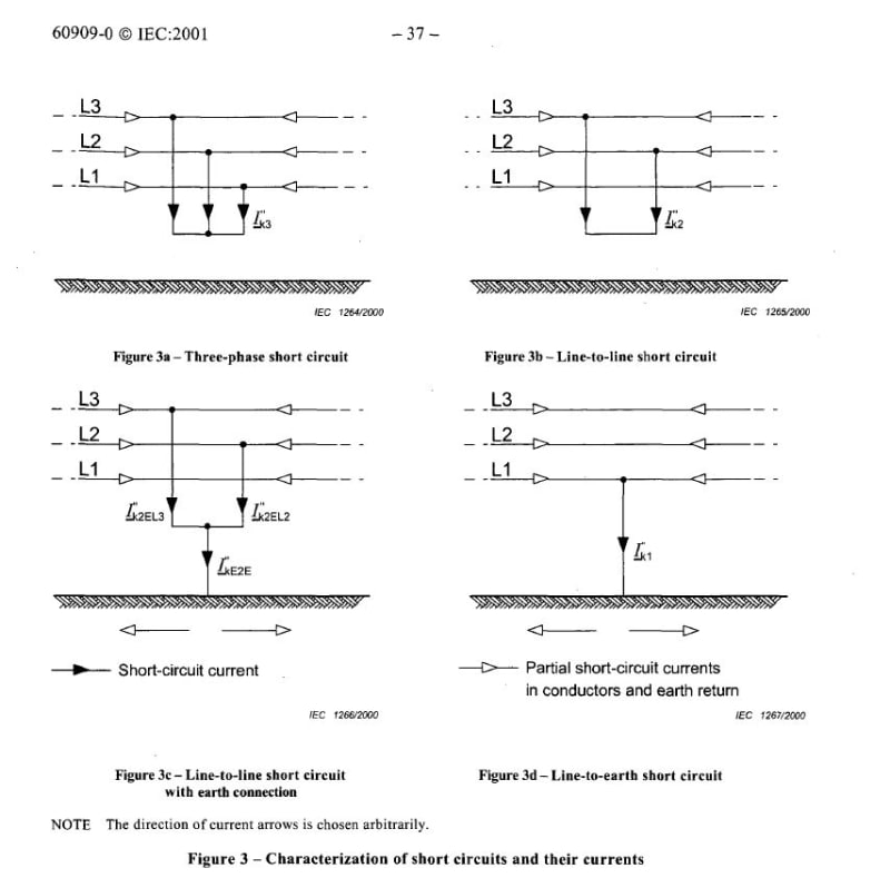
What type of installation is it (can we get a circuit diagram)?
If your installation is near the transformer on the secondary side then L-G should be the same as L-L-G, this is of course under the pretence that all the impedances are equal.
However! Since both L-G and L-L-G are dependent on the zero sequence they are therefore both dependent on the return path for the fault and the transformer/source earthing.
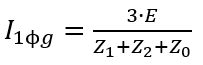
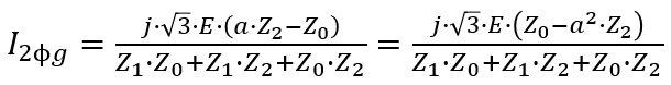
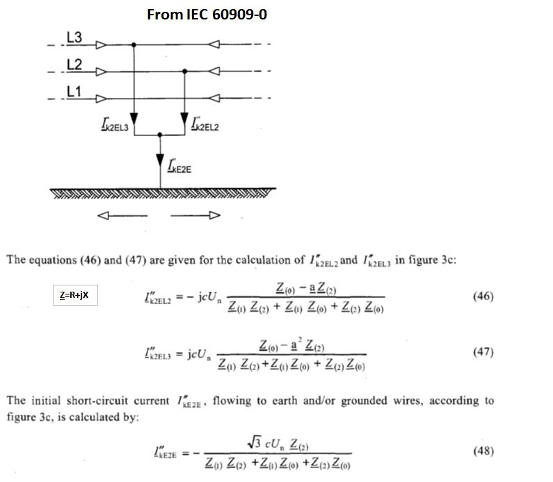
If we strictly look at the equations assuming E is the phase pre-fault voltage they will look like this:
A note about the L-L-G fault, The left and right hand side of the equation corresponds to a faulted phase, so let's say fault current in phase b corresponds to the left equation and phase c to the right equation. Then from a strictly mathematical perspective if Z0 is greater than Z1 or Z2 if they're equal. Then one phase will have a higher fault current than the other, which can be verified in a simulation tool or by just doing the calculation, although they shouldn't vary greatly to a point where this difference is significant. Then there's an entirely different equation that calculates the fault current in the ground
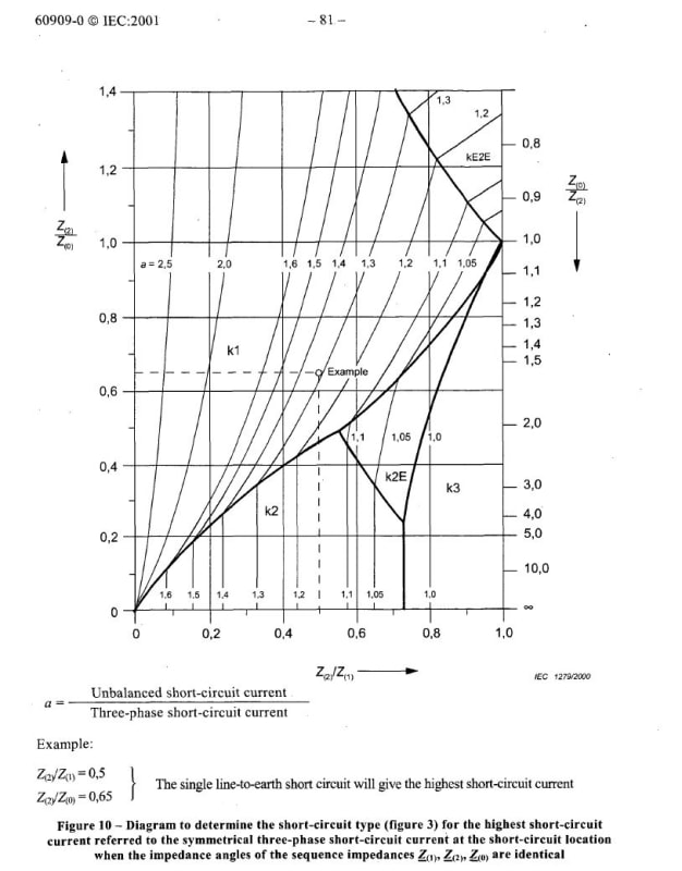
However if all sequence impedances are equal then the L-G and L-L-G faults are equal.
If Z0 is 0, then L-L-G will exceed the L-G short circuit.
All of this however is speaking strictly from a mathematical perspective and not a practical perspective, as I don't have the amount practical experience the majority in this forum has.
The point I'm trying to make: Look at your circuit, where does the fault happen, what's the return path (does it have a high or low impedance?) and what's the system earthing. All of these factors will affect the fault current in the two scenarios you're examining.