Continue to Site

Eng-Tips is the largest engineering community on the Internet

Intelligent Work Forums for Engineering Professionals

  • Congratulations waross on being selected by the Eng-Tips community for having the most helpful posts in the forums last week. Way to Go!

Joint design for a telescope mount 3

Status
Not open for further replies.

Deven_Patel

Mechanical
Aug 11, 2017
8
Hello,

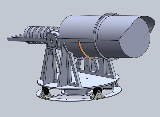
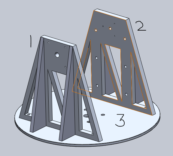
I'm working on an astronomical study project that entails building a mount for a telescope. I'm working on the mechanical aspect and I am designing the mount at the moment, but I've run into some questions about how I should go about designing the joints for the mounts (1&2 in the picture) and the platform (3 in the picture) that the mounts will be fixed to. I was thinking about designing flanges at the base of the mounts to fix them to the platform in a precise and secure manner. Reducing the propagation of mechanical vibrations that the platform may be subjected to is also a concern. Any thoughts about the flange idea? Or recommendations for another method?

Capture1_his0bt.png


Thanks in advance guys!

Deven Patel
 
Replies continue below

Recommended for you

What is the telescope weight and height of its horizontal pivot axis above plate nbr 3?

They plates are "drawn" as solids. Is that what you really intended?
How is the plate nbr 3 rotating, what is it rotating upon (another concrete pad?), and what is its axle?
How will you adjust the plate nbr 3 to be astronomically "flat"?
 
Below is the very preliminary assembly design. Please pay no mind to the interference of solids near the top of plates #1 and #2. I'm aware of this, it's obviously going to be corrected but has not been done just yet; I just posted the picture to give you guys a better idea of what it looks like.

Capture3_ifgkk2.png


The telescope weighs about 20kg, we are placing counterweights at the other end to balance the CG. We have an optical set-up as part of the payload that needs to be on the pivot axis between plates #1 and #2, which is the reason for not having our telescope's CG on the pivot axis. The pivot axis is about 400mm (15.748 inches) above plate #3.

Yes, I intended for them to be solids. What is the alternative?

It's a little hard to see in the picture above, but plate #3 is rotating on a rotatary platform, it will be fixed to plate #3 by 4 fasteners (you can see them near the center of the plate) that will transmit the torque to the plate.

I haven't made any considerations to make plate #3 astronomically flat; I'm not quite sure what that means, to be honest. Our mount will be able to rotate in 2 directions (i.e. it is an altitude-azimuth mount), so it will be able to correct for any mechanical imperfections. We think so, anyway, please shed light on this if I am missing something.

Thank you for the reply!

Deven Patel
 
Deven_Patel,

Would an interfacing flange be any better than screws coming up through your baseplate?

More importantly, how stiff is your baseplate? Have you worked out the torsional stiffness of your structure between the holes at the bottom centre, and your telescope mount points? Have you considered a one-sided telescope mount? I suspect that this will be easier to rigidify, and it may even be cheaper and simpler.

With optics, your problem is stiffness. Once you solve that, your structure should be very strong.

--
JHG
 
drawoh,

Thanks for the reply!

Screws coming up through my baseplate was my original idea, but I came across the flange idea and thought it was a better fit for my design. With flanges, I could use threaded bolts to make it more resistant to potential mechanical vibrations. I'm not an expert in fasteners so please give me your take on it!

I haven't calculated the torsional stiffness of my structure just yet; we will likely be choosing an aluminum alloy (a stiff one by the looks of it). A one-sided telescope mount was not considered because we have two motors that need to be on the pivot axis between the mount plates #1 and #2 (you can see one of those motors in the picture in my previous post).

Thank you for your input!

Deven Patel
 
Compositepro,

Thanks for the reply!

Before the project's design was started (before I was even on the team), it was decided that an Alt-Az mount was preferable to an Equatorial mount for the purpose of this project for a number of reasons. Time, cost, complexity and space constraints are the main reasons.

Thanks for the reference, though!

Deven Patel
 
Deven_Patel,

I recommend structural analysis now while you can change things. All aluminium alloys are approximately the same stiffness. I also recommend quickly and crudely trying out a one-sided mount. It may be better for structure as well as packaging machinery, like motors and controllers. That flat plate you have is not very stiff.

--
JHG
 
drawoh,

I will definitely be performing a structural analysis ASAP. After your recommendation, I feel as if I'm misunderstanding the concept of the "one-sided" mount, can you elaborate? Or, perhaps, refer me to a website that has an example of a one-sided mount? I'm open to making these kinds of changes so I'd like to better understand your proposition.

Thanks again for your support!

Deven Patel
 
Deven_Patel,

Remove one of your vertical pieces. On the other vertical structure, work out some sort of rigid bearing. It must resist moment as well as X and Y[ ]forces. What you have there is a large fork. You have quite a length of structure extending from one side of your telescope to the opposite side. When you need rigidity, the shorter your structure is, the better. Since it is shorter, it can be very much thicker and more rigid.

In general, when you are designing something, you should try two or three (or more!) general approaches. I am sure you have multiple problems to solve. The good approach may not be at all obvious until you try something else.

--
JHG
 
drawoh,

Thanks for the clarification! That's what I thought you meant. I will definitely give it a try and make a decision accordingly.

I agree! We never considered a one-sided approach but, before the fork design was thought of, we tried 2 other approaches; unfortunately, we ran into conflicts with the optical design and those ideas didn't pan out because of it.

Deven Patel
 
You might also look at vibration, resonant frequencies.
If you are looking to have this track then you need very smooth and precise motion, generic 'stiff and flat' are not good enough.
Every little motion imperfection will cause your motors to hunt, and disrupt the image.

= = = = = = = = = = = = = = = = = = = =
P.E. Metallurgy, Plymouth Tube
 
No. Rockler Woodworking Supply has a 1000 pound-rated lazy susan at 12" roller diameter with 4x mounting holes on both baseplate and rotating plate that is only $9.99, available overnight from their shop.
The proposed "wheel and roller" assembly will slip and fail with no side-movement control and poor alignment (no brakes nor controls!) on the caster wheels. (The casters alone will be $12.00 to 35.00 each!)

For the lower baseplate, use 4x screw pad/level adjusters under each corner of a wide baseplate (24 inches each side, or slightly more) that mounts the lazy Susan assembly. The equatorial mount (as mentioned above) is then mounted to the rotating baseplate.

Your lower baseplate should include a magnetic compass (for faster rough alignment to north; and 360 degree marks all the way around. (Coarse align first, then adjustment, then final fine-tune. )

You are amateur fabricators and designers - that's fine. But it will be much, much easier to weld simple mild steel than aluminum. And much less expensive when you do get another shop to fabricate the telescope mount. If you cut and weld it yourself, plasma-arc cutting and simple MIG welding on simple steel shapes is a valuable learning experience for your group.

Steel will move much less with thermal changes as the night cools, or as elevation and locations change through the year. It is heavier than Al, but much much less expensive to purchase too.
 
For simple steel shapes, and adequate (simple) filler welds on 1/4 (6 mm) or 3/8 (10 mm) or 1/2 inch (12 mm) thick steel or the equivilent. I'd use 2 inch long fillet welds, with a 1-1/2 to 2 inch gap between each weld. Alternate the fillet welds on each side of the T-shaped joint. On angles, where you choose not to buy simple angle iron shapes, but to fabricate your own, as amateurs you should be prudent and conservative and weld the entire length.

But expect stretch and shrink in the weld joint as the welds cool: the movement of the welds as they cool WILL MOVE your entire assembly! Use heavy C-clamps and magnets to hold pieces as you tack weld before final fabrication. Final machine the final positions of the telescope holder clamps and bolts AFTER assembly and welding.
 
EdStainless,

We are definitely taking a look at vibrations and resonant frequencies. I'm happy you mentioned the need for the precise and smooth motion, it's something that I've been hoping to optimize from its current, preliminary state. Do you have any recommendations on how to achieve this? I'm taking a look at racookpe1978's suggestion from this afternoon, but I'd love your take on it as well!

Deven Patel
 
High stiffness and vibration isolation are a bit conflicting. You might want to go high stiffness/high damping.
 
Status
Not open for further replies.

Part and Inventory Search

Sponsor