Continue to Site

Eng-Tips is the largest engineering community on the Internet

Intelligent Work Forums for Engineering Professionals

  • Congratulations KootK on being selected by the Eng-Tips community for having the most helpful posts in the forums last week. Way to Go!

ISO Simultaneous requirement 1998 vs 2016

Status
Not open for further replies.

Kedu

Mechanical
May 9, 2017
193
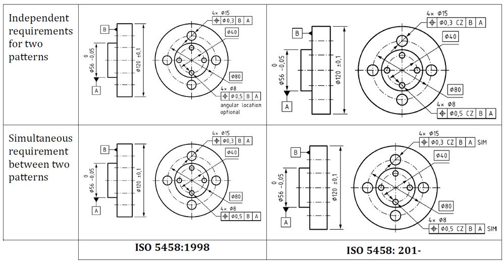
Q: Has ISO updated its simultaneous requirement definition from 1998 to 2016?

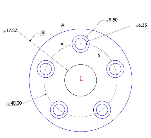
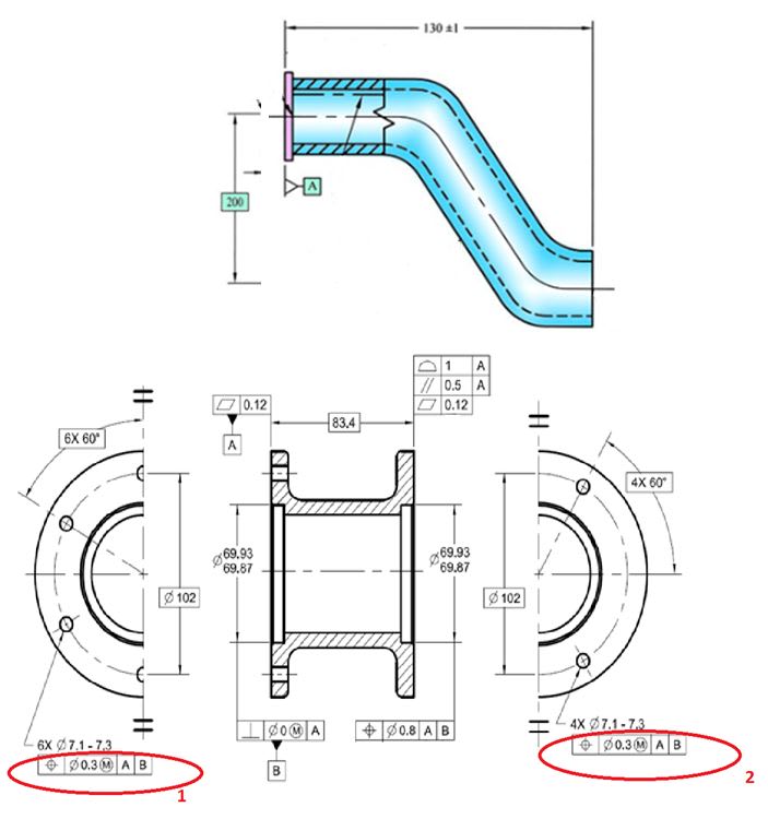
Background: One position (5 holes) has double CZ modifiers and one SIM and the second position (4 holes) has CZ and SZ and also one SIM. Same datums on both. Is simultaneous requirement implied for both sets of holes?

For my life I am not understanding those callouts.
I need some basic understanding of the simultaneous requirements in ISO. Any good discussions to point out to?

What I knew (until today) is CZ = simultaneous requirement in ISO.
 
Replies continue below

Recommended for you

Kedu,

It might help others if we first clarify that you are talking about update of ISO 5458 standard for position tolerance.

That update has not taken place yet. It is expected to happen later this year. So the only valid version to use is the one from 1998 which defines simultaneous requirement rule but only for pattern of features that share the same datum axis.

In addition, because a lot of other important changes in ISO GPS language happened since then, it is worth to remember that the '98 document has become severly outdated.

Per my knowledge, the 2018 document will set rules for establishing patterns of features and these rules will be fully compliant with the principle of independency that is a fundament of GPS philosophy. In other words, if functional intent is to treat two or more geometrical requirements as one, like in your case, there has to be an extra annotation/modifier used in conjuction with these requirements that will tell that the requirements are not to be treated individually. This is where modifiers like CZ, SZ or SIM will come into play.

Unfortunately, as I am not in a possesion of any draft of new ISO 5458, I am not able to tell you at the moment how exactly it will work.

Hope that helps at least a bit.
 
Pmarc,
Thank you. We received a draft print (for our evaluation only, no quote needed at this time) from our customer. They are using ISO GPS.
It’s not the first time when we see CZ “combined zone” on their print and I always read it as simultaneous requirement (rightfully or not). I am using ISO 1101 and its applicable (hopefully released) related standards.

Looks like someone interpreted “The specification element CZ can be used to create a pattern;” as a “good-to-go” to put it in the FCF on positional callouts for the patterns of the holes.

Let me ask you: how would you enforce simultaneous requirement in 1998 (ISO 5458) for two sets of holes (one set made of 5 holes and the other of 4 holes) located with position to A, B (similar, more or less, to Fig 4-4, ASME Y14-5-2009)?
 
Kedu,

Not sure I understand your question correctly. If ISO 5458:1998 is used on the print, and both groups are positioned to the same datums, there is nothing to enforce because by default these two callouts constitute simultaneous requirement.

I assume the problem is that the print you received for evaluation shows modifiers that in year 1998 (if they existed) would not be needed at all.

BTW: CZ modifier can be read as simultaneous requirement but only within a group of features controlled by the same single geometric callout. If there are two groups of features controlled by two geometric callouts with CZ, then, as of today, there is no way to define simultaneity between the two groups in ISO, unless they share a common axis. As far as I know, ISO 5458:2018 is going to change that by introducing SIM modifier.
 
Maybe this could be little help (cannot guarantee that it's coming from reliable source):

large


"For every expert there is an equal and opposite expert"
Arthur C. Clarke Profiles of the future
 
Yes, CH. That is exactly what I was trying to say/describe.
 
No, ISO 5458 is not used on the print. ISO 1101 it is and I’ve been told that’s invoking all the other ISO GPS standards (sic, even ISO 2768, my rethoric question??).
Not sure I want to dig thru all the documentation / contractual agreements between us and the customer (as the relation is going back 40 years or so). Might say something about all supporting/applicable standards…or latest standard applied when the drawing is to be released/ approved.

And yes, CZ is used within a group of features controlled by the same single geometric callout.

If the two flanges in fig 4-4 are offset (basic dimension is shown) from each other you wouldn’t say that they share a common axis, don’t you?

CH pictures are very helpful. Do you have “Means this” explanations?

The difference from my case is that in the same position FCF a double CZ is used for the 5 holes pattern and CZ SZ modifiers for the 4 holes pattern. Then the customer’s designer added SIM on both placed beneath the FCF. And As I stated before, I am not understanding it.
It is true that the print is not released/ in production yet and they just “get our feet wet”, but looks like might not be correct either. Or at least not in agreement with the current released standard.
 
Kedu,
You are lucky, 2768 is exception of a sort - it will not be invoked automatically unless you specify it together with tolerance classes and/or everything else: ISO 2768-mH(E) or something like that

"For every expert there is an equal and opposite expert"
Arthur C. Clarke Profiles of the future

 
Thank you CH and pmarc,
My follow up question would be: if only ISO 1101 is shown on the drawing does it mean ISO 5458 is invoked automatically? (consider for a second we are talking about ISO 5458-1998 –released one—not about 201- shown in your attachment, but I don’t think make any difference)

 
Kedu,
Per paragraph 2, Normative References, of ISO 1101:2012, ISO 5458:1998 is one of the documents that is "indispensible for application" of ISO 1101.

Per paragraph 2, Normative References, of ISO 1101:2017, the latest revision of ISO 5458 (including any ammendments) is "indispensible for application" of ISO 1101.

So theoretically the answer depends on the version of 1101 that is referenced on the drawing. But practically this does not matter in this particular case, because no ammendment of 5458 has been published since 1998.

But please do not ask me how I would deal with a configuration management mess that will be introduced to the drawings that exist now and refer to ISO 1101:2017 after new version of 5458 gets issued.
 
ISO_Q_q6zpp9.jpg


And because I cannot publish the print, I am trying to show the concept depicted . Please see the attached picture and consider:

position 1 I have CZ CZ inside FCF and SIM outside

position 2 shown CZ SZ inside FCF and SIM outside


2 flanges, one of each end separated by basic dimension. There are more slots and holes on these end flanges , but for now I think is irrelevant.
 
Kedu,
I may be mistaken here, but per my knowledge SIM modifier has not been defined in any officially released GPS standard yet. So it looks like your customer is using a tolerancing practice/tool from an unuofficial document (a draft version possibly). I guess it is fair enough reason to ask them for a at least a hint on how to interpret those callouts. Otherwise you (and we here too) are just left with guessing.

But if you want, we can play that game. You said that there are other holes and slots on both flanges. Are they possibly controlled with the same position tolerance (the same callout) as the holes in question?
 
pmarc,

pmarc said:
But please do not ask me how I would deal with a configuration management mess....
No, I won't.

pmarc said:
So theoretically the answer depends on the version of 1101...
Well, no ISO 1101 date/year is shown. Should we "assume" the latest revision applies? We always did it (assumed) in the past. Now I am questioning if was the right thing to do.
Therefore, ISO 1101-2017 would be my "non-educated" choice.

Now it is my time to ask you: don't ask me what is happening when a new ISO 1101 revision would be in place/ would be released ? Would that change the product definition/ functional requirements (if this dangerous assumption is in place)?

pmarc said:
But if you want, we can play that game

Let me do some homework and get clarification from my customer about "SIM" and "ISO 5458 draft 201xx??" and the game is on. Like it!

By the way: How would you deal with a configuration management mess.....? Just kidding [bigsmile]
Thank you very much for your input.

Have a great weekend and Happy Mother's Day!

 
Follow-up on this conversation:

ISO 5458 -2016. I did not realize that is not a released standard, but just a draft. Has been confirmed by the customer. Probably that’s why the drawing is not released, just FYI –evaluation- only.
Anyway, here is more info for our discussion… I am trying to decode the meaning of the positional callouts below:

My side note: I am thinking that size and tolerance values of the C’bores and thru holes are not necessary important for our discussion that’s why I am using a picture from 2009 “modified” with my callouts that I’m trying to understand.

Left flange:
Pos 1: 5 holes and their 5 applicable c’bores RFS to A –planar surface--primary and B –cylinder- secondary with CZ CZ and SIM (see Fig 7-24 from Y14.5-2009, for reference only)

2x; 5x Ø6.3-6.4 (for flange’s thru holes) and Ø 9.4-9.6 (for flange’s C’Bores)
Position Ø 1mm CZ CZ to A primary B secoundary SIM


Right flange:

Pos 2A: 2x; 4x Ø 2.1- 2.3 holes (2 different B.C.D.’s)
Ø 0.75mm -RFS to A –planar surface--primary and B –cylinder- secondary with CZ SZ and SIM

and
Pos 2B: 2x; 4x slots 4.4 - 5.1 size (4 slots on flange’s ID and 4 flange’s OD)
1.5mm -RFS to A –planar surface--primary and B –cylinder- secondary with CZ CZ

The closest figure from 2009 I can get for right flange is 7-31.
 
A picture, sketch, hand marked napkin values thousands of words.
Interested myself how does ISO enforce angular alignment between features.
 
FLG_1_afcvyz.png
FLG_2_jg2seb.png


As I am interested how this thread is playing out I've placed the sketches in the text--embedded--instead of the above attachments. Hopefully the OP does not mind.
 
Kedu,
Could you also sketch how the position tolerance frames look like?
 
Flange 1 (left or first picture in greenimi's figures)
2x; 5x Ø6.3-6.4 (for flange’s thru holes) and Ø 9.4-9.6 (for flange’s C’Bores)
Position Ø 1mm RFS CZ CZ to A primary B secondary and outside FCF SIM


Flange 2 (right picture)
2x; 4x Ø 2.1- 2.3 holes
Position Ø 0.75mm RFS CZ SZ to A primary B secondary and outside FCF SIM

2x; 4x slots 4.4 - 5.1
Position 1.5mm RFS CZ CZ to A primary and B secondary (no SIM outside FCF)

Dimensions shown in pictures are nominal.


Kedu,

This is how I would interpret the callouts:

Flange 1:
- first CZ (combined zone) modifier means that five Ø1 position tolerance zones for Ø6.3-6.4 thru holes are spaced basic 72 degrees apart;
- first CZ modifier also means that another five Ø1 position tolerance zones for Ø9.4-9.6 c'bores are spaced basic 72 degrees apart;
- second CZ modifier means that both groups of five Ø1 position tolerance zones consitute a pattern, i.e. both groups of five position tolerance zones are perfectly clocked to each other (basic 0 degrees dimension between the groups).

Flange 2 - position callout #1:
- first CZ modifier means that four Ø0.75 position tolerance zones for Ø2.1-2.3 holes at pitch diameter of 33 are spaced basic 90 degrees apart;
- first CZ modifier also means that another four Ø0.75 position tolerance zones for Ø2.1-2.3 holes at pitch diameter of 25 are spaced basic 90 degrees apart;
- SZ modifier means that both groups of four Ø0.75 position tolerance zones are not clocked to each other.

Flange 2 - position callout #2:
- first CZ modifier means that four 1.5 position tolerance zones for 4.4-5.1 ID slots are spaced basic 90 degrees apart;
- first CZ modifier also means that four 1.5 position tolerance zones for 4.4-5.1 OD slots are spaced basic 90 degrees apart;
- second CZ modifier means that both groups of four 1.5 position tolerance zones consitute a pattern, i.e. both groups of four position tolerance zones are perfectly clocked to each other (basic 45 degrees between the groups).

SIM modifiers applied to the position callout in Flange 1 and position callout #1 in Flange 2 mean that both patterns of tolerance zones constitute another bigger pattern. And here, assuming that my guess is correct, I would have one comment - to me it is not clear which of the two groups of four Ø0.75 position tolerance zones the pattern of ten Ø1 position tolerance zones would have to be clocked to.

No SIM modifier after the position callout #2 in Flange 2 means that the pattern of eight 1.5 position tolerance zones for slots does not have to be clocked to other holes and c'bores in question at all.
 
Pmarc,
Looks like ISO and ASME are handling clocking (angular) relationship between those features from an entire different perspective and they are 180 degrees apart (two opposite directions).

I've requested a copy of the draft from our customer. They will send relevant pages. I guess I’ll have to learn the theory of the new standard…

Then probably I will be able to answer your question about “….to me it is not clear which of the two groups of four Ø0.75 position tolerance zones the pattern of ten Ø1 position tolerance zones would have to be clocked to”.

In the meantime I appreciate very much your time spent helping me understanding “the new way” of using simultaneous requirements in ISO. Kind of make sense. Everything independent unless otherwise specified.


By the way, are they “legally” allowed to use a “draft” standard ? Does not seem logical to use a standard that has not been released, at least in my opinion and in my uneducated mind. Why companies are allowed to purchase and use draft versions of ISO standards?


Status
Not open for further replies.

Part and Inventory Search

Sponsor