pmarc,
Since ISO 14406-1 is withdrawn, do you know, by any chance, where did they move those picture? Which released (if any) ISO standard has now this explanation?
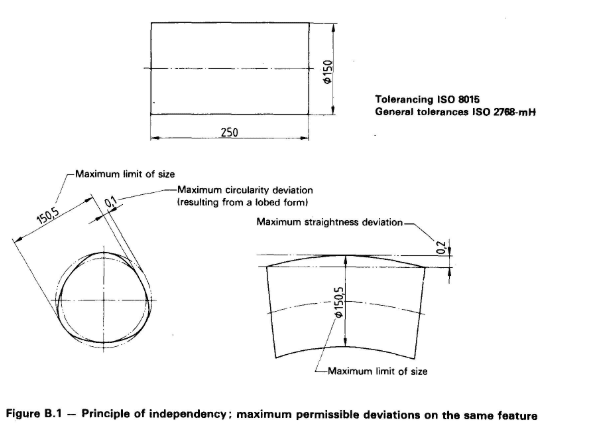
On the same token, I know ISO 8015: 1985 had a nice figure (2) where on a section view of a cylindrical surface showing maximum limit of size and maximum circularity deviation (lobed form).
For my life, I do not edit (KNOW) where this picture has been moved / which standard, because in ISO 8015 - 2011 is nowhere to be found.
Do you know, from the top of your head, where these good and instructive picture were moved. Hopefully, they were not just eliminated from the standards entirely.