That is very similar to the hydraulic governor on a diesel CR.
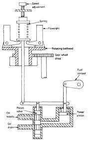
This is a very good illustration for explanation but some refinements are missing.
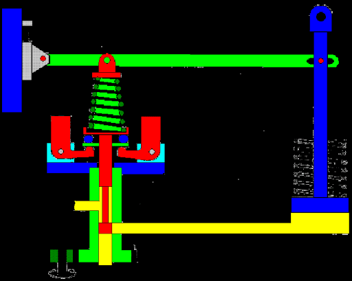
The horizontal arm across the top is the droop feedback.
Not shown; A mechanism to vary the mechanical advantage and so adjust the percentage droop.
Yellow is hydraulic oil.
Not shown; an oil pump. Some used engine oil pressure. Some had an oil reservoir and a small gear pump to supply operating oil pressure.
A further common refinement was the addition of four check valves so that the governor could be rotated in either direction depending on the application and the pump would still deliver operating oil.
The leftmost yellow port is the supply port for pressure oil.
The lowest yellow port in the green body is the discharge port.
Not shown: A method of varying the pressure on the speeder spring and so adjust the speed setpoint
The speeder spring is the conical spring above the centrifugal weights.
The blue block on the upper left supports the fulcrum of the droop arm.
Moving this fulcrum up or down is one way of adjusting the bias force on the speeder spring.
A stand-alone generator:
This may have a screw adjustment, locked with a lock nut.
A universal governor, meant for general application but suitable for generator use may have a speed adjusting knob.
A small electric motor may be used to adjust the bias force on the speeder spring.
A parallel operated set;
This will have either a speed adjusting knob or an electric motor to adjust the bias force on the speeder spring and thus the speed setpoint.
In our plant we had electric motors on the governors. The control was a three position spring return to center switch on the switchboard. Faster-Off-Slower.
The power piston on the right, which controlled the fuel rack on the engine, was controlled by volume, not pressure.
As you can see, the pilot valve, the lowest red part, covers the discharge port very closely.
With any slight increase in speed the centrifugal weights will raise the pilot valve and allow some of the oil supporting the power piston to be discharged, thus lowering the piston and reducing the throttle position.
With any slight decrease in speed the centrifugal weights will lower the pilot valve and allow pressure oil to be admitted to raise the power piston, thus increasing the throttle position.
Leakage on an older, worn, governor.
Any leakage would allow the power piston to slowly reduce the fuel delivery.
The governor would react by allowing more oil past the pilot valve to maintain the position of the pilot valve.
There may be a small percentage error in the speed.
However the operator would typically be setting the speed by the frequency, not the physical position of the adjustment and so the error would tend to be self correcting.
An exception would be a cold start. If an engine was started cold and put online, the leakage or bypass of the cold oil would be less.
When the oil warmed up to normal operating temperature the operator may tweak the setting a few percent.
Next up: mechanical versus hydraulic governors.
Bill
--------------------
"Why not the best?"
Jimmy Carter
![[bigsmile]](/data/assets/smilies/bigsmile.gif "[bigsmile] [bigsmile]") ]
]