Continue to Site

Eng-Tips is the largest engineering community on the Internet

Intelligent Work Forums for Engineering Professionals

  • Congratulations cowski on being selected by the Eng-Tips community for having the most helpful posts in the forums last week. Way to Go!

Is this a diaphragm? 3

Status
Not open for further replies.

WARose

Structural
Mar 17, 2011
5,594
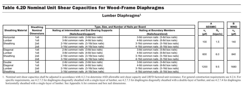
Need a sanity check here: I was asked to look at a wood building the other day.....and one thing that caught my eye was the diaphragm(s). They consisted of a bunch 2x4's (and so forth) laid down flat and nailed down (perpendicular to) to a bunch of 2x8's @ 16" o.c..

So you have a wood floor that is about 1.5" thick.....but the spacing between the 2x4 boards is about 1/4" (or 3/8" in some cases).

So can this be called a diaphragm (with all those gaps; and the fact the gaps are continuous)?
 
Replies continue below

Recommended for you

In Canada we only accept 1x or 2x material as diaphragm if it is installed diagonally. And they limit the capacity to 8 kN/m.
 
I would not call it a diaphragm although it can offer some resistance to deformation. I doubt the magnitude it can offer is very much. I also have no idea how you would calculate the allowed capacity.
 
I suppose if you considered it a Vierendeel truss, it would have a lot of capacity. But you would need to verify the connections can transfer moment.

DaveAtkins
 
The table below from AWC SDPSW is applicable, is it not? I'm not sure about a limitation on the gaps.

c02_jqqczl.jpg


C01_t6pqov.jpg
 
I have never seen noticed the horizontal lumber option. I notice it does not have any 2x4s or 1x4 but does not explain why. It may be because the nails are not far enough apart to offer the resistance. But at least you have some design values to work with.
 
You don’t get much out of it. The nailed connections can twist a lot before it engages.
 
The twisting can be restrained by nail couples in each individual member if the couples are present.

Mike McCann, PE, SE (WA, HI)


The two nail couple mechanism certainly exists but it relies on loading the supporting member perpendicular to grain across its narrow face which is, of course, soft and generally abominable. Hence most engineers' reluctance to brace anything important this way.
 
True, and I would never condone or use the couples, considering the connections an extra resistance mechanism. Hard to quantify and difficult to control.

Basically using the same mechanism though on a skip sheathing roof system.

I would be interested in seeing the system tested and rated.

Mike McCann, PE, SE (WA, HI)


I am under the impression that the nail coupes ARE the resistance mechanism that gets you some capacity for this situation. If someone knows otherwise, however, I'd love to hear about it. It has a particular importance with respect to gapping I think. If the couple IS the capacity, then the gaps probably don't matter much within reason. vierendeel trusses like Dave said. If the capacity comes from something then all bets are off with respect to the gaps until we identify what that something else is.
 
I wonder if the research that created the chart was very in-depth. Instinctively, a 1x6 and a 2x8 should not have the same strength. But that is me making a snap judgement. Let me apply some science, 1x6=6 and 2x8 = 16 The only difference in 6 and 16 is the 1. 1x100 is a 100. I guess they are about the same strength.
 
Those capacities must be governed by the connections, that's why the capacity is the same regardless of 1x6 or 2x10 decking. And the reason diagonal sheathing is drastically higher is because I don't believe it relies on the nail couple, just nails in shear both in the same direction. To me that all seems very intuitive.
 
I agree with the connections almost certainly being the governing parameter. And, because of that, I'd only expect the capacity of a 2x8 system to exceed that of a 1x6 system meaningfully if the outer nails were more spread out more with the 2x8 system (lever arm). Given that the table doesn't have anything to say about nail spacing, I'm guessing that's assumed to be based on whatever conventional minimums are specified elsewhere.
 
I'll throw my hat into the ring on the side of the nail couples providing the resistance. Consider an outdoor deck. This is exactly the mechanism used to resist wind, seismic, and occupant lateral loads. Consider the prescriptive requirement for tension ties at each end of the deck - it's because the the deck is considered to act as a cantilevered diaphragm with lateral load resistance coming from the ledger and the couple formed by the tie and a compression block.

See this article by Structure Magazine and pay particular attention to the first line under Observed Damaged in "Results and Discussion."
 
The resistance is from the nailed connections. Go bang a short bit of decking into a joist and try to twist it off. You’ll see. It’s partly nail shear and partly clamping friction.

It’s better with no gaps between boards. Friction between boards helps.
 
This document contains our local New Zealand guidance on assessing and analysing these types of diaphragms, they are often present in 100 year old plus URM (unreinforced masonry buildings) round these parts.

As others have noted their strength and stiffness comes from the nails and sometimes friction between boards and/or boards and joists.
 
Status
Not open for further replies.

Part and Inventory Search

Sponsor