Tek-Tips is the largest IT community on the Internet today!

Members share and learn making Tek-Tips Forums the best source of peer-reviewed technical information on the Internet!

  • Congratulations JAE on being selected by the Eng-Tips community for having the most helpful posts in the forums last week. Way to Go!

Intersection of two parts

  • Thread starter Thread starter fedeflr
  • Start date Start date
F

fedeflr

Guest
Hi all,
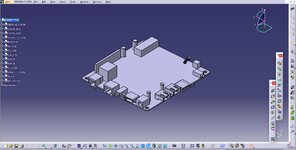
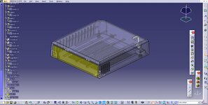
Its my first post but Ive been checking the blog for a while and would like to ask you guys a question, I am having troubles making the ports (hdmi, sd card, usb...) in a plastic housing, the thing is that I have the two parts of it and the PCBA with all ports (in different files):

View attachment 1857
View attachment 1858

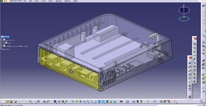
I want to do the holes for the ports perfectly aligned but I really can not come up with a solution, I tried with an assembly but it didnt work:

View attachment 1859

Do you guys know a way to do the holes for the ports properly?
 

Attachments

  • ffdcvsdc.jpg
    ffdcvsdc.jpg
    131.1 KB · Views: 4
  • fvdcsqedcs.jpg
    fvdcsqedcs.jpg
    169.5 KB · Views: 3
  • ggfdfqred.jpg
    ggfdfqred.jpg
    189.1 KB · Views: 3
go to generative shape design - use boundary comment to project holes and ports - extrude them - lastly use trim comment- if you wanna scale projected boundaries use scale before extrude
 
Sure; model the housings in the context of the assembly.

1. Fully position (constrain) all the parts (housings and cards) in the assembly and save the assembly along with all the parts.

2. With the assembly open, double-click on the housing you want to add the holes to. In the tree, the housing have a blue background to indicate this is the part you're working on (and CATIA should switch to the Part Design workbench). Now build your hole sketch and project the geometry from other parts, or constrain the new geometry to geometry in other parts. Continue to work on that active (blue) part using other geometry as if everything was one big part.

3. If having all the parts on the screen is too much, make the assembly active (blue) and hide some of the part instances that you don't need to see.

4. Right-click on a housing and choose DEFINE IN NEW WINDOW to see and work on that housing all by itself. Go back to the assembly when you need to project geometry between parts, or check that everything is aligned correctly.

5. When you're done with one housing, double-click on the other housing to make it active (blue background) and project/constrain geometry to make the mating port holes in the that part.

6. When you're done, use the File + SAVE MANAGEMENT to save the modified parts and assembly. Do not rename files or copy files, until you fully understand this process.

7. If the cards or ports get moved in the future, the housing holes will move also (with Update), as long as the assembly is open.

8. Contextual design is a very powerful feature of CATIA. My comments above are just a quick, abbreviated tutorial in some the things you can do. Just be careful to verify which part/assembly is actively being worked on.
 
Thanks a lot, very useful. I did fast something that Ive been trying to solve for days. Have a nice day!!
 

Part and Inventory Search

Sponsor

Back
Top