Continue to Site

Eng-Tips is the largest engineering community on the Internet

Intelligent Work Forums for Engineering Professionals

  • Congratulations waross on being selected by the Eng-Tips community for having the most helpful posts in the forums last week. Way to Go!

Interrupted FOS classification, ASME Y14.5-2009

Status
Not open for further replies.

Burunduk

Mechanical
May 2, 2019
2,524
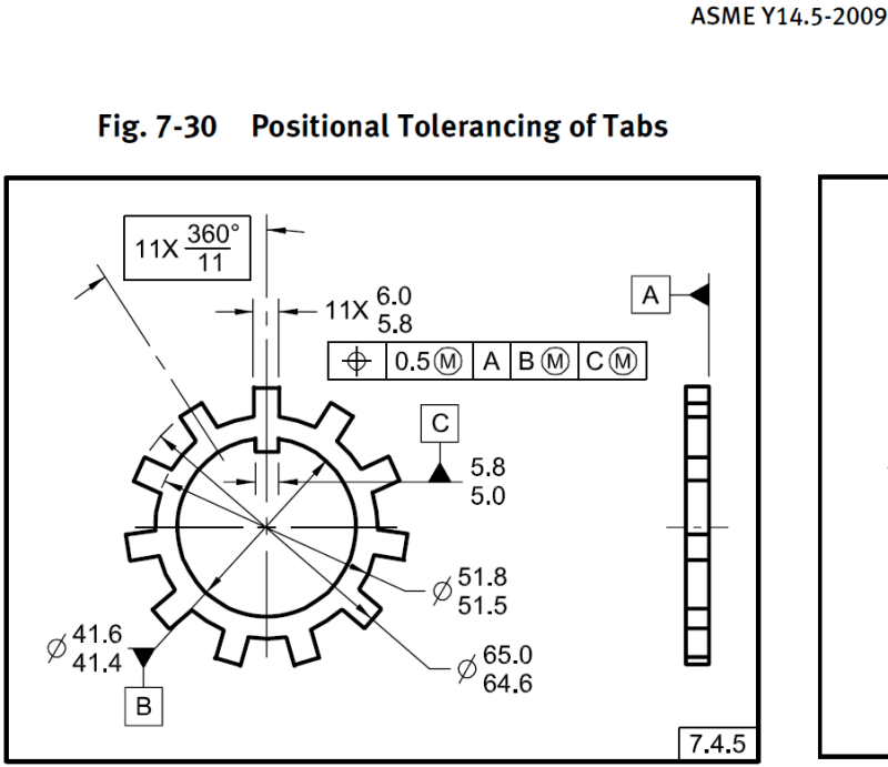
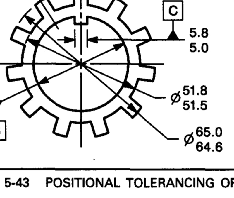
Is the 64.6-65.9 OD in fig. 7-30 in Y14.5-2009 a regular or irregular feature of size?

If it is an irregular FOS, Rule#1 does not apply to it, so the distinction may be practically important.

One way to support the stance that it is Irregular FOS is to say it is Irregular type A, as it is too interrupted to be considered "one cylindrical surface" and more importantly it has no opposed points, so if a less than 180° radius is invalid as a regular feature of size, this one should be invalid too, from the same reason/convention. Yet it is directly toleranced and can be contained by an actual mating envelope that is a cylinder, making it Irregular type A.

Opinions?

 
Replies continue below

Recommended for you

The diameter is given as 64.6-65.0, and yes, it would seem to be an irregular FOS. And I would agree that it's Type A since it perfectly conforms to the definition of being "contained by an actual mating envelope that is a...cylinder." Other than that, I'm not sure what your specific question is.

John-Paul Belanger
Certified Sr. GD&T Professional
Geometric Learning Systems
 
Hi all,

Would it be a legal callout to add <CF> next to the dimension? Or since the individual features are not a feature of size, all 11 features cannot be one feature of size? So it cannot be a continuous feature (of size)?

1_sgdvnz.png
 
I would not recommend CF in this case. Not because of a FOS vs. non-FOS issue, but because the ends of the teeth are flat rather than rounded. If they were rounded (with a radius) then it would be more conducive to a diameter with the CF modifier.

John-Paul Belanger
Certified Sr. GD&T Professional
Geometric Learning Systems
 
Belanger,
I didn't notice that the ends of the teeth were flat rather than rounded, but now that you say it - it does look that way, at least in the 2009 version.
Curiously, in the 1994 version of the figure, 5-43, they end look rounded, at least in my eyes.

20200828_102830_zjd8dt.jpg


If the teeth ends are flat, what is measured by the diameter tolerance? Is the 64.6-65.0 dimension measured over the sharp corners?

Anyway, I tend to agree that this should be classified as an irregular FOS per the 2009 standard as I suggested in the OP and you confirmed, but I think it may not be that obvious. As I mentioned above this figure was featured in the 94' version of the standard. It uses limit tolerancing, which is preserved almost exclusively for features of size, and it doesn't look like one of the typical exceptions (like depth of a hole, chamfer or radius). FOS prior to the 2009 version were only "regular" (but obviously weren't called that way as the different types didn't exist yet). Therefore it's not unlikely that the committee members that originally added that figure were considering the collection of the outer faces of the tabs as a FOS, the only type that was at the time, which is now called "regular feature of size". What do you think?
 

Burunduk,

I agree with you. In the 1994 version, it is definitely not a feature of size. To me, that is a mistake that was never detected.

It is very weird that those features were converted to planar faces. Not sure if it was intentional or a simple print/PDF error?

Does anyone have the 2018 version? I am curious if this drawing is still there and if the ends are flat or curved.


Belanger,
Assuming all the 11 features are cylindrical faces, converting 11 surfaces that are not features of size to 1 continuous feature of size with the <CF> symbol bothers me somehow due to the fact that we are changing the type of the feature(s).
 
Looks curved to me in 2018. One has to wonder exactly how that mixup was even made in 2009 since a diameter is clearly specified and the dimension line is clearly attached to a curved extension line. Something was overridden somewhere when it shouldn't have been. One could assume that it refers to the maximum inscribed or minimum circumscribed diameter but its not clear which it would refer to, and I doubt that was the intent.

flat_vs_curved_hdojan.png
 
Probably it's a matter of which students were available to do the work combined with a change in the software being used.

Hint -
1 setlinejoin
1 setlinecap
 

All the arcs in that drawing look like lines, polylines. No student would make arcs polylines on purpose. I think it is a conversion error from CAD to PDF. I have seen similar errors, for instance when you make an A-size PDF from an E-size drawing. All the lines and fonts get screwed up.
 
A student might not see that they are supposed to be arcs. The conversion is, as I suggested, a factor that is part of the software, but I think that line-width failure to make extension lines narrower is 100% under the control of whatever engineering graphics student could be getting extra credit for.

Neither the CAD operator or the CAD software has an effect on the poor QA used in accepting these graphics for publication.
 
Status
Not open for further replies.

Part and Inventory Search

Sponsor