sendithard,
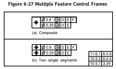
First off, just to get it out of the way before I make any assumptions since you already stated you do not have access to the standard I want to make sure I clearly define the difference between a composite and multiple single segment tolerance. A multiple single segment allows constraint of both translation and rotation in the lower segments, its basically just a special case of two or more separately applied profile (or position) tolerances.
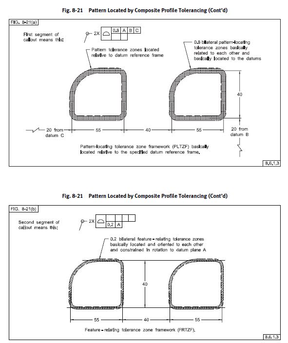
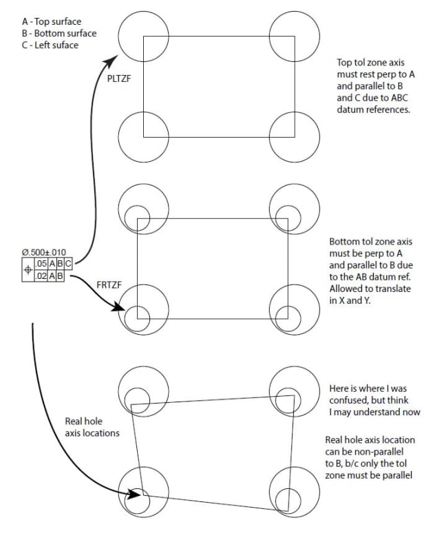
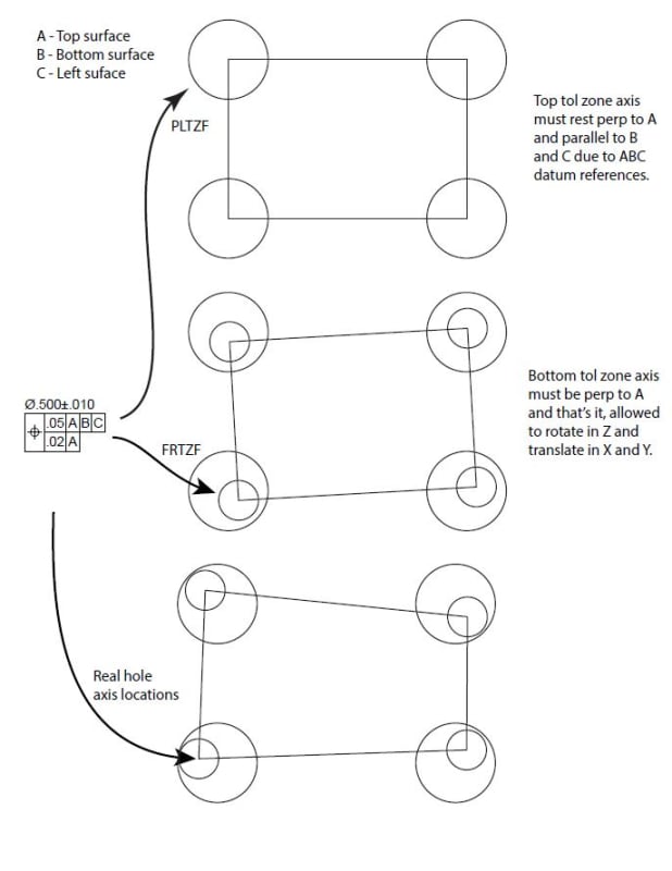
A composite tolerance, which you have shown here, does NOT allow constraint of translation in the lower segments (FRTZF) - ONLY ROTATATION. Ie: any location with respect to your datum features does NOT apply in the lower segments/FRTZF of a composite tolerance.
Note the differences in notation (in this case position, but of course same applies for profile):
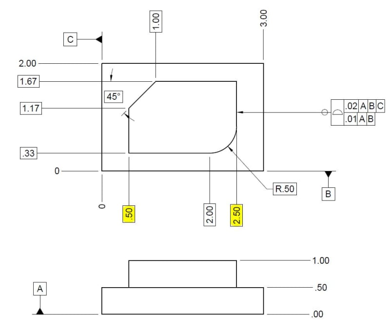
Okay, so a few items which might help your understanding. First, basic dimensions are theoretically exact - period. It does not matter from what reference they are defined, as long as the geometry is fully defined somehow, the exact method makes no difference as long as it is clear. For example it does not matter if the highlighted dimensions are given as ordinate dimensions as shown from the left edge, as separate width dimensions wrt each other [0.5] and [2.0], or ordinate dimensions from the right edge the result is the same (assuming its okay the rightmost dimension can be basic, which its not currently).
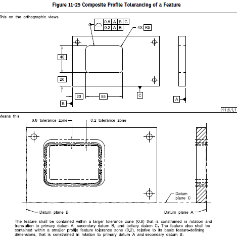
Secondly, we use these basic dimensions for a profile tolerance to define our "true profile" - which is essentially just that, the theoretically exact geometry defined by basic dimensions. Your profile tolerance zone, is a zone of a width defined by your FCF in this case equally disposed about your true profile. The addition/removal of datum features does not fundamentally change that - the only additional constraint is that in addition to satisfying the requirements of size and form dictated by the profile tolerance, it must also be constrained in location and orientation as applicable to the specified datum features.
would you just do the math from the existing basic dimensions?
Per my above, yes. As long as the geometry is fully defined, you can derive any necessary dimensions.
I think the bottom tol zone dictates the tol zone each feature can deviate from each other.
Both tolerance zones must be satisfied. The feature must be within the upper segment (PLTZF) a zone .02 wide equally disposed about the true profile and constrained to |A|B|C|. The feature must also be within the lower segment (FRTZF) a zone .01 wide equally disposed about the true profile and constrained in
rotation only to |A|B|. Thats it. The effect is that the .01 zone effectively "floats" within the .02 zone as anything outside that is non-conforming, but they can essentially be considered/verified separately.
since the bottom tol zone includes the A,B drf would the .33 dimension still be required to be measured within the tighter .01 zone b/c Datum B is in the drf...whereas if it were datumless would each surface just be held to each other without concern over distance from Datum B and perpendicularity to Datum A?
Individual dimensions aren't really verified/measured like that with a profile tolerance - even if one might be led to believe that by the way some QC departments set up their inspection reports. As I noted above, the surface must be within the respective profile tolerances when constrained to the applicable datum features. The .33 dimension is not really something to be individually verified, but in turn locates your true profile - ie: when datum feature B is invoked/specified in a DRF
that can constrain location (ie: NOT the lower segment/FRTZF of a composite tolerance*) your true profile is located .33 away from the datum feature simulator for B and your tolerance zone is equally disposed about this true profile. This concept expands to any datum features in a DRF which constrain location, and obviously with a datumless tolerance there is no location/rotation constraint - only that the surface must be within a tolerance zone equally disposed about the true profile not constrained to any particular DRF.
*Lower segments/FRZTF of a composite tolerance can only constrain rotational DOF even if B is specified. This is NOT the case for the upper segment/PLTZF.
I know thats a lot to take in and a lot of words. This is where the standard is helpful. See below for an example of what I mean, note how the lower segment essentially floats within the upper segment.