Continue to Site

Eng-Tips is the largest engineering community on the Internet

Intelligent Work Forums for Engineering Professionals

  • Congratulations KootK on being selected by the Eng-Tips community for having the most helpful posts in the forums last week. Way to Go!

Internal brick wall - lateral restraint at top 7

Status
Not open for further replies.

LR11

Structural
Sep 13, 2001
169
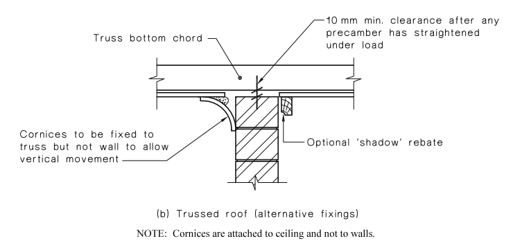
I've been trying to find out if there's a requirement to restrain internal brick walls which act as a shear wall.
This would be at the top, to the roof or roof truss members.
This would be a common scenario to any dwelling with internal brick walls.

At the moment I have a gap in between ceiling and top of wall (see image).

Capture_jmgysq.png
 
Replies continue below

Recommended for you

When it comes to interior partitions, I believe there is a certain height which can be left unbraced, or height/width ratio. Don't remember the code reference of top of my head. Keep in mind, gap might have to be sealed per fire code requirements.

Now if it indeed a shear wall as OP mentioned, how are those shear forces transferred if its left unrestrained on top?
 
A single wythe brick wall is a veneer, not normally considered to be structural. If the wall is built up with more than one wythe and adequate as a cantilever to resist lateral pressure (5 psf by code), it could be unsupported at top. It is not clear how such a wall could receive much shear load if not connected at the top.

BA
 
Thanks for responding. Just to clarify the shear load is along the length as shown.
These do act to restrain against wind loads.
The query relates to whether lateral restraints are required at the top.

Capture2_u6luli.png
 
I understood the question. The wall could serve as a shear wall without being connected at the top provided it could stand as a cantilever. Alternatively, it could serve as a shear wall if laterally supported by other walls or partitions at an acceptable spacing. A brick wall which cannot stand as a cantilever and has no other lateral support should not be used at all, let alone as a shear wall.


BA
 
I agree with BAretired here; the wall is either a cantilever wall with some kind of clips to transfer the lateral load from the diaphragm or the wall should be braced for seismic forces and out of plane live loading to act as a pin-pin wall, in which case you would still need to address shear transfer.
 
BAretired said:
I understood the question. The wall could serve as a shear wall without being connected at the top provided it could stand as a cantilever. Alternatively, it could serve as a shear wall if laterally supported by other walls or partitions at an acceptable spacing. A brick wall which cannot stand as a cantilever and has no other lateral support should not be used at all, let alone as a shear wall.

Wait so, don't all shear walls have to be attached to the diaphragm along its length for them to be considered shear walls? How else would diaphragm forces get into the shear wall? Unless there are other collector members to transfer the shear into either end of the wall.
 
Without restrain on top, the walls forming a free standing T beam system. Stability of the stem is in question.

image_zl9dfr.png
 
Thanks for the responses.
I found something in AS 4773.1. It appears the ceiling & cornices are used as horizontal restraint.
Does this sound correct? It must be right.

Ceiling_eo2sxx.png
 
Lateral restraint is needed from both sides. Whether or not the detail accomplishes that is debatable. I wonder why the 'shadow' rebate is optional. Perhaps it means it isn't required, or perhaps it means it could be used in lieu of a cornice. If the former, I disagree. If the latter, I wouldn't quibble.

I agree with manaf engineering's comment. The only shear getting into the wall is from exterior walls bearing against it.

BA
 
A decorative cornice is absolutely not adequate, nor being used in that detail for lateral restraint. The gap is to avoid roof loads on the wall. As noted the corniced is attached to the ceiling to allow vertical movement of the truss.

I am not familiar with the Australian Building Code you are referencing, however, from AS 4773.1 section 1.1b...

"The tops of all walls are laterally supported by a roof or floor structure acting as a diaphragm with the exception of parapets, chimneys and cantilevers in accordance with Clause 14.9"

From the way you've described it I do not agree that this wall is acting as a shear wall. It sounds like an interior partition that's unbraced out of plane and if its a single wythe it's not designed as a cantilever.

I'd recommend you seek out a local structural engineer.
 
Harbringer, hang on a second.
Firstly I am skeptical as well but my reading of the code seems that it's an option.
The clause below mentions the Figure above.

I'm obviously not an expert but it seems to me that details in the building industry are leaner.
I was surprised to find out that ceilings plasterboard is used as a diaphragm to transmit horizontal loads.

Section_6.4_kqfvlb.png
 
I presume this is for a house in Australia?

All walls require horizontal support at the top except for the exceptions noted in Cl 6.4 of AS4773.

By shadow rebate, I think they just mean the small notch shown in the picture.

You still need to establish a load path for the in plane shear load to get into the wall.
 
I guess that will teach me to comment on other countries building codes. I am aware of gyp walls and ceilings being used as lateral elements (though in my area that's mostly in residential and I rarely do residential work).

However, unless a cornice means something widely different in Australia than in the U.S. it doesn't pass the smell test. It looks like a 1/2" piece of decorative crown moulding trim nailed to the ceiling. Just because it's in your code doesn't make it good engineering.

I don't know what your region's seismicity is so maybe it's not an issue for you.
 
Harbringer said:
I am aware of gyp walls and ceilings being used as lateral elements (though in my area that's mostly in residential and I rarely do residential work).

AS4773 is generally only used for residential work.
 
Harbringer, OK I was thinking the same thing anyway.
From what I gather in my reading over the last couple of weeks is that a lot of elements, including foundations are designed in terms of budget in mind, being just robust enough but with some degree of give.
Retrograde, yes this was for a residential house.

Where I was coming from is that I want to limit the interface with the truss manufacturer. Their design is theirs, I don't know which walls they will bear on, if any.
Following a review of their fabrication drawings, was thinking of calling up some trimmers to transfer lateral loads.

But the question actually came from the perceptive of wind load directly on the external walls.

I don't know if I have a definite way forward but will have to review at a later date.

 
In Australia (and I'm sure it is similar in other countries) the Codes for residential house design tend to be more rules-of-thumb and deemed-to-comply, and do not require the level of in-depth calculation needed for larger buildings.
 
Back to your question of wind load on the exterior walls. I don't think you've provided any details about the ext wall construction, but how much wind trib do you think will go to this interior wall? Depends on materials and detailing but maybe 4ft?

You could do a FEA model of the wall elevation for OOP loading or a compatibility analysis for the wall in-plane deflection and the diaphragm deflection...realistically without a shear transfer from the diaphragm into the wall, it will see very little wind load.

If you don't know which walls the trusses will bear on, how do you design the foundation? I would imagine you have different prescriptive design details for bearing and non-bearing walls just like we do. In the U.S. we dictate which walls are bearing and the truss manufacturer designs for our bearing locations per our drawings (this is true for residential and commercial).
 
LR11 said:
Harbringer, hang on a second.
Firstly I am skeptical as well but my reading of the code seems that it's an option.
The clause below mentions the Figure above.

I'm obviously not an expert but it seems to me that details in the building industry are leaner.
I was surprised to find out that ceilings plasterboard is used as a diaphragm to transmit horizontal loads.

I'm not saying you're saying this, but just to be clear, the detail you have showing with the "cornices" could possibly be enough to brace the top of this partition wall. And I can also see how ceiling plasterboards can act as part of a diaphragm. But still in no way will the wall in that detail act as a shear wall.

Doesn't matter if ceiling plasterboards carry lateral load or not, there is no way for them to transfer into your wall. Bracing a top of a wall because it won't be stable to out of plane indoor loads (5 psf) is entirely a different issue than using the wall as a shear wall for lateral analysis purposes. If you are going to depend on this wall as a shear wall then you'll need a positive attachment to the wall in the horizontal direction while allowing for vertical deflection.
 
Sorry but I'm not relying on plasterboard carrying load, just bracing laterally, the 2.5% usually mentioned.
Maybe people are getting confused with the query and the sketches presented initially.
Just think, typical dwelling, two leaf/wythe external wall, single leaf internal walls which take the wind shear load. What is enough lateral restraint.

The detail above is used, we know that.
(1) It's used even considering the out of plane loads mentioned.
(2) What I don't know for sure is ... if the walls carrying wind load, are able to used the detail in the Figure above, where the cornice offers lateral restraint.


Status
Not open for further replies.

Part and Inventory Search

Sponsor