jnelson33
Mechanical
- Mar 7, 2018
- 53
**DISCLAIMER: I am not looking for the true knitty-gritty, science-the-sh@t out of this explanation, only the common sense, yes or no, this is a good design, here are some pointers explanation.**
Hello All,
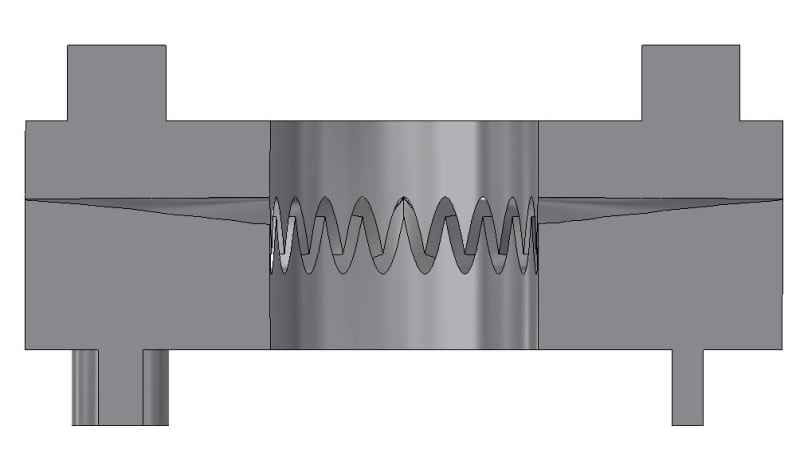
I am making a geared-locking part for use on vehicles in all sorts of driving conditions. In order to help some of our products mount on tube chassis vehicles, they will need a clamp. The varying diameter clamp fastens to the tube on the car, in between that are two geared halves followed by the bracket for the part fastening to the clamp. The fastening is all done via one Grade 12.9 alloy steel ISO 4762 M8x1.25 socket head screw. The primary part is connected to that bracket/gear/clamp assembly.
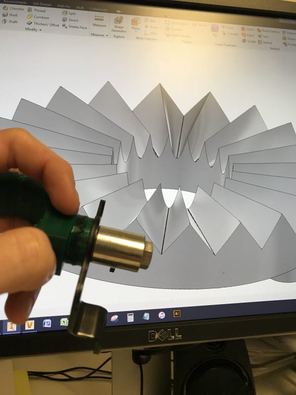
I have provided a rough picture for how this will generally look. In real life, the correct M8 screw will be used without that long spacer. The idea is that the diecast geared halves allow for adjustment of our part on the tube chassis vehicles so that they can be made level again.
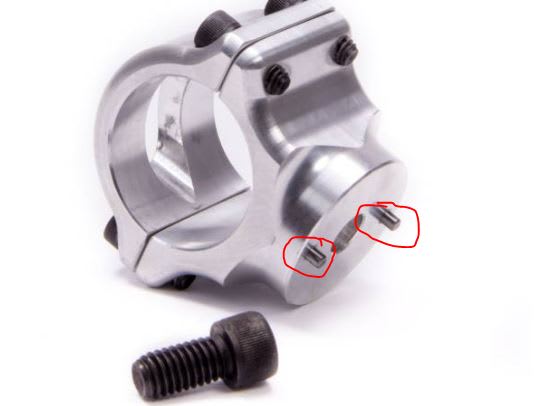
Another company has done something similar to this, but I can't stand making parts to 50 year old CNC/manufacturing standards, plus all that drilling and pressing of pins is just insane when not needed! This is what my boss wanted me to copy, but I knew it wasn't a good way to make things.
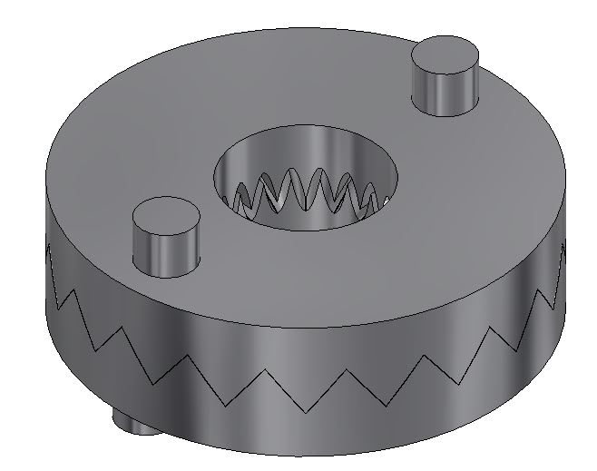
My boss does not believe the gear design that I have made will keep it locked since the teeth don't make contact along the whole face, a decent point of course, but one I believe to be insignificant for this application. His other comments are, "...need to tweak the CAD model and prints for this to square off or round off the sharp edges of the gears so that we can send this off for quoting as a die cast part." His background is software engineering, so that's why I'm here; I need to bound this off some more appropriate internet colleagues since my discussions with him just end in my way or the highway.
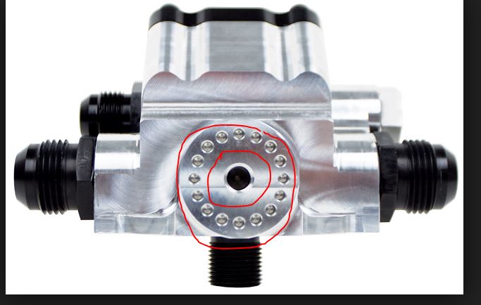
Btw, my idea was inspired by my drumming hardware. My boss does like that the "faces mesh fully" on those parts; what gear standard do y'all think this is loosely based on, I thought face spur gears which led to crown gears?
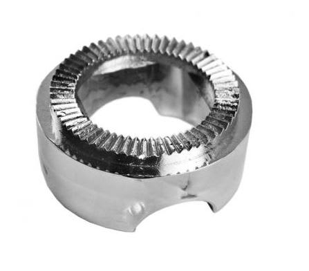
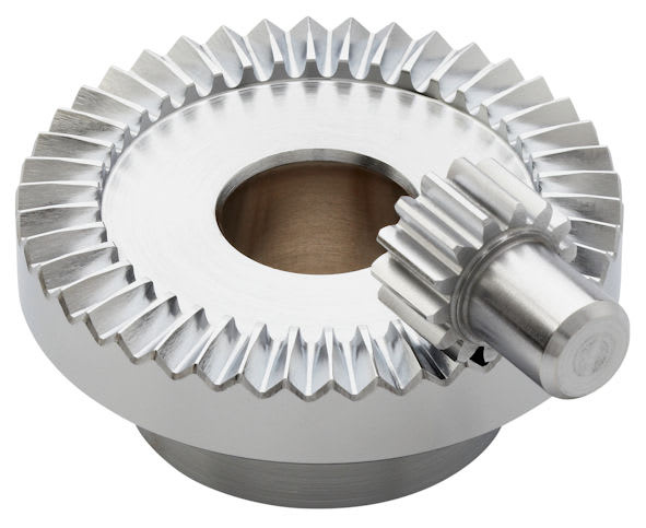
I searched for a while when I first tackled this design, and found the crown gear design that I'm using now. The only problem I see with the design I used is that it's designed for propulsion which is why the insides don't mesh.
Link
Hello All,
I am making a geared-locking part for use on vehicles in all sorts of driving conditions. In order to help some of our products mount on tube chassis vehicles, they will need a clamp. The varying diameter clamp fastens to the tube on the car, in between that are two geared halves followed by the bracket for the part fastening to the clamp. The fastening is all done via one Grade 12.9 alloy steel ISO 4762 M8x1.25 socket head screw. The primary part is connected to that bracket/gear/clamp assembly.
I have provided a rough picture for how this will generally look. In real life, the correct M8 screw will be used without that long spacer. The idea is that the diecast geared halves allow for adjustment of our part on the tube chassis vehicles so that they can be made level again.
Another company has done something similar to this, but I can't stand making parts to 50 year old CNC/manufacturing standards, plus all that drilling and pressing of pins is just insane when not needed! This is what my boss wanted me to copy, but I knew it wasn't a good way to make things.
My boss does not believe the gear design that I have made will keep it locked since the teeth don't make contact along the whole face, a decent point of course, but one I believe to be insignificant for this application. His other comments are, "...need to tweak the CAD model and prints for this to square off or round off the sharp edges of the gears so that we can send this off for quoting as a die cast part." His background is software engineering, so that's why I'm here; I need to bound this off some more appropriate internet colleagues since my discussions with him just end in my way or the highway.
Btw, my idea was inspired by my drumming hardware. My boss does like that the "faces mesh fully" on those parts; what gear standard do y'all think this is loosely based on, I thought face spur gears which led to crown gears?
I searched for a while when I first tackled this design, and found the crown gear design that I'm using now. The only problem I see with the design I used is that it's designed for propulsion which is why the insides don't mesh.
Link
