A bit of back story for context. 45 years ago in an electronics class, the instructor passed out heavy duty, 5 Henry audio Chokes to the class members, We were all told to find the inductance.
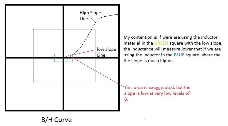
We did, and the general consensus was answer was it was a few milliHenries. And we were on to the next assignment, there was no discussion about why we had the millihenries instead of Henries. This got me started on finding an answer answer and I ended up learning about B/H curves. The answer I ended up with is that our measurement current was so small that the H field line slope was still very shallow (10*). It wasn't until you got to much higher H field (more current flow) that the slope got up to say 45* instead of 10*. An exaggerated drawing to help explain. i.e. if you look at a B/H curve, at the very beginning the slope is very low, but as H increases the slope increases. And, in my mind the inductance is higher.

First let me know if I misunderstand how slope of B affects inductance.
Now, assuming my thinking is correct, this is my question.
I'm winding transformers for RF antennas where signal strength is measured in uV and the equipment used to test these transformers is in millivolts. So, are we getting a true measurement of the primary and secondary inductances? I'm thinking a low signal levels inductance would be much lower.
Another thing I factor in, commercial receivers have very tiny transformers on the input (OD 3/16" or less), I think this puts the B higher on the curve even at low RF voltages. My latest need is a 9 to 1 impeadance transformation, I can use a 0.5" OD core or a tiny Minicircuits transformer, now I wonder if the minicircuits will be better at the low uV signal levels.
Please share your thoughts on this topic.
Thanks, Mikek
PS, after writing my question I did find this video with a good B/H graph of the low level non-linearity at the 5:00 mark. Also the domains shown before and at saturation, made me think, that it takes a certain amount of energy to move the domains, at low levels we may not be moving many are any thus low inductance.
We did, and the general consensus was answer was it was a few milliHenries. And we were on to the next assignment, there was no discussion about why we had the millihenries instead of Henries. This got me started on finding an answer answer and I ended up learning about B/H curves. The answer I ended up with is that our measurement current was so small that the H field line slope was still very shallow (10*). It wasn't until you got to much higher H field (more current flow) that the slope got up to say 45* instead of 10*. An exaggerated drawing to help explain. i.e. if you look at a B/H curve, at the very beginning the slope is very low, but as H increases the slope increases. And, in my mind the inductance is higher.

First let me know if I misunderstand how slope of B affects inductance.
Now, assuming my thinking is correct, this is my question.
I'm winding transformers for RF antennas where signal strength is measured in uV and the equipment used to test these transformers is in millivolts. So, are we getting a true measurement of the primary and secondary inductances? I'm thinking a low signal levels inductance would be much lower.
Another thing I factor in, commercial receivers have very tiny transformers on the input (OD 3/16" or less), I think this puts the B higher on the curve even at low RF voltages. My latest need is a 9 to 1 impeadance transformation, I can use a 0.5" OD core or a tiny Minicircuits transformer, now I wonder if the minicircuits will be better at the low uV signal levels.
Please share your thoughts on this topic.
Thanks, Mikek
PS, after writing my question I did find this video with a good B/H graph of the low level non-linearity at the 5:00 mark. Also the domains shown before and at saturation, made me think, that it takes a certain amount of energy to move the domains, at low levels we may not be moving many are any thus low inductance.
