Belanger said:
I would say that your datums B and C are not directly opposed, so they are not covered by Rule #1 and thus they get the general profile tolerance.
John-Paul Belanger,
Why those two datum features (which lets pretend are not covered by rule#1) are getting the general profile?
What rule#1 has to do with the relationship between features (a.k.a. mutual relationship between primary and secondary -maybe perpendicularity, or relationship between tertiary datum feature and its higher precedence datums)?
I do not think that there is any relationship, therefore, rule#1 enforced or not, it's a moot point. Rule#1 wouldn't establish anyway any orientation relationship (of datum feature B) to the primary. The same for C.
Again, I am asking the question from the REQUIRED relationship between datum features (secondary to primary and tertiary with primary and secondary).
Also, what rule#1 has to do with the enforcement of the UOS (default profile) onto the datum features B and C?
Evan,
axym said:
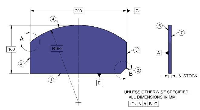
Datum features B and C on the L-shaped part drawing are not features of size, because the datum feature labels are not directly in line with the dimension lines.
I know that, but you did not answer my question: Are the datum features B and C subject to the default profile note?
If answering this question in a direct way will create some sort of controversy, I understand that, and I will accept that you do not want to go there. I was just curious how would you answer it. Is this another swamp?
John-Paul Belanger,
In this discussion, looks like Evan it saying that the rule#1 is applicable EVEN if the features are not totally opposed.
axym said:
axym (Industrial)
15 Sep 15 17:00
greenimi,
I'm glad that the thread is getting to some interesting outcomes. Your questions tend to make us dig deep and extract the subtle details. Keep in mind that the writers of GD&T textbooks and exercise books (and even standards) can only get into the intricacies to a certain extent, without losing most of their audience. People want things to be simple and easy, not complicated and difficult. I know from experience that it is much easier to make money glossing over these subtleties than it is addressing them. I'll stop there before I get into a self-righteous, bitter rant ;^).
CH,
I would say that Rule #1 still applies, even with features that are not perfectly opposed. Assessing the feature's conformance to a boundary is straightforward, even if the feature has unopposed areas.
Again, to me the difficulty lies in the actual local size. It's an old, shop-worn tolerancing tool that serves well for parts that one wants to be able to inspect with a caliper or mic. But for this tool to work, certain conditions have to be in place (such as opposed geometry, and form error that is relatively small). When these conditions are not satisfied, it breaks down and becomes ambiguous. It's just not as robust as zone-based geometric tolerances.
Evan Janeshewski
Axymetrix Quality Engineering Inc.
www.axymetrix.ca
Evan,
Are you maintaining your opinion shown above? Again, just for my own edification.
All,
Which datum feature is REGULAR feature of size in fig 7-40/2018.
Figure 7-40 Irregular and Regular Features of Size as Datum Features
Again, I am talking about the datum features (don't came back and say the holes are regular FOS in that figure, because the holes are not datum features)
") Aren't we?
Aren't we?