Eng-Tips is the largest forum for Engineering Professionals on the Internet.

Members share and learn making Eng-Tips Forums the best source of engineering information on the Internet!

  • Congratulations JStephen on being selected by the Eng-Tips community for having the most helpful posts in the forums last week. Way to Go!

IC 4017 Switching as a remote switch jumping why

zoo123

Mechanical
Joined
Aug 29, 2004
Messages
26
Location
IN
Dear friends,

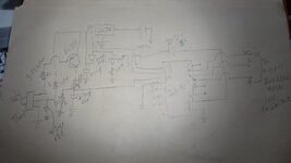
i am nOT Electronics specialist but mechanical, and hands on knowledge on electronics pcb design. i am making a remote IR SWITCHING for a pcb to change from a manual mode to auto mode. with three switch pressing using IR REMOTE TRANSMITTER and IR Receiver ( TSOP 1738 ). I use 7805 from 12v dc input, with RC Circuits for debounce avoidance, ( picked from unknown supplier).

I use output pins of IC 4017 Pin no : 3, pin no 2 pin no: 4 and then through PIN NO 7 I am trying to reset the IC Back again . But, i do not see pin 7 helping me to reset , and the other unconnected outpins are getting initiated though. so, for 4 pressings to work, i press 30 to 50 presses randomly and it is pain for me now. COULD Some one help me. attached files and a video too . thanks

i also added a 4.7UF 63V capacitor between resistor output from TSOP Recently but , i do not see any debounce disappearing.
 

Attachments

i also added a 4.7UF 63V capacitor between resistor output from TSOP Recently but , i do not see any debounce disappearing.
Your schematic says otherwise.

What time constant are you trying to achieve?
 
yes i did not include it in schematic. upon a check with a few i did it but it does not work out now. may be it is an outlayer .

HONESTLY On the time constant details, i did not dwell on it. could you pl. open up my thinking process and crush my poor brain pl.
 

Attachments

  • ir receiver with 4017 clarification3_25jul25.jpg
    ir receiver with 4017 clarification3_25jul25.jpg
    113.1 KB · Views: 2
Last edited:
TSOP 1738 appears to be an IR -> signal converter. It converts the modulated IR signal into a demodulated logic level pulse stream.

4017 is a decade counter. It looks like the demodulated stream is being sent to the 4017 CLK (clock) input, so, depending on the IR remote it's like giving a prize wheel a spin.

I have no idea what the data stream from the IR remote looks like, but since you are looking at only 3 outputs of the possible 10 you only have a 30% chance of seeing any result and only 10% chance of getting the result you want. If the IR remote includes even numbers of pulses and you keep selecting that button, you may simply loop past whatever choice you want.

It looks to me as if you are trying to duplicate another setup as "manual" and "auto" mode aren't really part of this circuit.

In a schematic for a device that turns one input on and off (toggle) Pin 4 (output) is tied to the RESET pin (RST) so that sending a single pulse toggles from position Q0 to Q1 (resets device)

Since no output is connected to RST yours simply free-wheels through all the outputs.

This should help explain the way the IR controls work:

 
Thank you for the reply.

TSOP ir receiver receives signals at 38KHZ IS What i understand ( bookish / internet ). In addition, the output signal goes low from high and hence a PNP TRANS.( BC558or BC177) Is used ( the no. variation is the plastic pack Vs metal packaging).

the IC4017 architecture, allows it switch in a pattern of pin out 3 , 2, 4, 7, 10, 1, 5, 6, 9, 11. I dont know why it is this way. But, this is it. Hence, i trigger 3 times for a customer to know my other side of this circuit operates on manual mode , and auto mode. ( tHIS is totally out of scope for this question of mine, hence i did not confuse more pl. excuse).

you, can see in the video that switches from 3, 2, 4 and never comes back to 3 again, that must happen by default as i had hooked back the pin no. 7 to reset once again. But, it is erroneous and comes back to this 3, 2,4 cycle once again after 50 presses of the IR TRANSMITTER BUTTON, OR 25 PRESSES OR Very random, that is not clear. i also see that the outputs , 10 to output 11 goes high, and surprising to me why the pin 7 is not outputing and resetting the IC Counter back again. hence my pain. not sure why it is freewheeling. Thank you. seek your help.
 
Each IR button press generates a large number of transitions. You don't get just one pulse for each button press.

Have you checked the voltage on pin 7? It may be the voltage drop across the diode is too high to reset the chip.
 
Thank you. I beleive i checked the voltage on the pin, Not sure i saw it at High( 4.5 to 5.1volts) at any time. may be i can for a short while remove ZD and put a jumper and chk it. not sure why the ZD was added. i just copy it from an unknown source without knowing th eneed for it.
 
The schematic diagram is better for people helping you if you put the pin functional name next to each pin.

I also find that taking time to make a clean drawing rather than a hasty pencil sketch can also find problems.
 
Reset is asynchronous, the instant pin 7 rises, it will reset the counter and instantaneously falls again. If you want pin 7 to stay high for a reasonable amount of time, you need to gate it with the clock input.
 

Part and Inventory Search

Sponsor

Back
Top