Continue to Site

Eng-Tips is the largest engineering community on the Internet

Intelligent Work Forums for Engineering Professionals

  • Congratulations waross on being selected by the Eng-Tips community for having the most helpful posts in the forums last week. Way to Go!

I need help in Strength of Materials.

Status
Not open for further replies.

hanna2222

Student
Mar 23, 2021
1
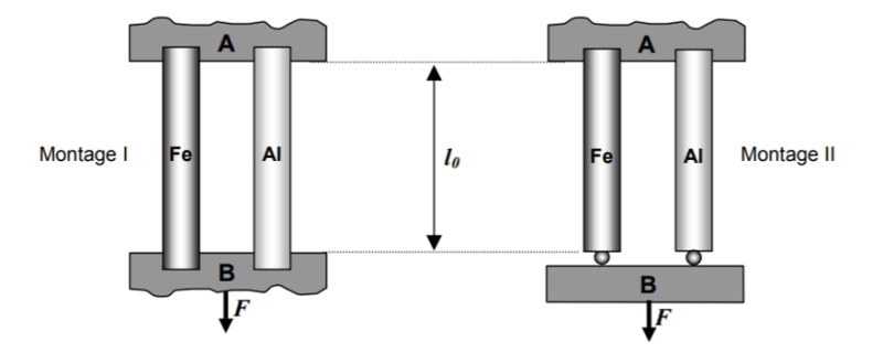
Hello everyone, in one solved problem in Strength of Materials, it was mentioned that the applied force on each bar for montage II is F/2 , even though they're made of different materials : Steel and Aluminum. Can you please explain to me why ? I'd be really grateful .
RDM_h9a2ay.png
 
Replies continue below

Recommended for you

hanna2222,

I assume the two bars have the same cross-sectional area.

If there was a mechanism that held member[ ]B exactly parallel to member[ ]A, then the two bars would see the same strain, and the less flexible steel bar would see three times the stress, and force. The elastic moduli are Esteel=210GPa, Ealum=70GPa.

In the absence of such a mechanism, this is a simple statics problem, and the two bars see the same force, and same stress. The aluminium bar will see more strain, due to its lower elastic modulus.

--
JHG
 
Another way of looking at it (repeats what drawoh just said, in different words).

Stop thinking about strength of materials for a second. Just look on member B and its three attachment points as a simple lever.

Once everything has finished moving, the only things that affect the forces in the specimens are the applied force, F, and the relative distances of their attachment points from the point where the force is applied. If both distances are the same, the forces will both be the same.

Top Tip: Everything you have already learnt remains true even after the syllabus moves onto the next topic.

A.
 
It is clear what the writer is trying to illustrate. Force F is half way between two bars and the reaction is F/2 for each bar. It is not necessary to assume the bar areas are equal.

Small deformations are ignored in this analysis. If the right bar stretches more than the left, Bar B rotates clockwise, moving force F vertically downward and to the left (closer to the Fe bar). The magnitude of horizontal movement depends on the depth of Bar B.

So, in practice, the bar with the larger A*E will take a little more load.

BA
 
If the top supports in Montage II are considered fixed and the bottom connections pinned, differences in bar properties, specifically A*E, will produce variable tension and bending moment in the vertical bars if small deformations are considered.

BA
 
If there are two rigid connections at the top and two pin supports at the bottom, then member B is a simple span beam with a point load and the force in each of the vertical bars is zero.

And finally, if there are two rigid connections at the top and two pin connections at the bottom, the system is not in equilibrium; members A, B and the two vertical bars hurtle through space with an acceleration of F/m where m is the combined mass of the group.

So the answer to the question depends on one's interpretation of the sketch.


BA
 
Status
Not open for further replies.

Part and Inventory Search

Sponsor