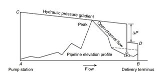
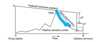
I don't think so. I think it just represents where full pipe flow exists. Above the dashed line is open channel flow just as it indicates in the diagram. I believe the pressure curve is the thick line as shown. Up to the valve the energy of the fluid is still the entire static head at the peak plus velocity head minus some head loss due to friction so hydraulic curve is still relatively high. With slack flow all static head at the peak is converted to velocity head as it falls down the pipe with losses due to friction making the hydraulic line drop slightly.
On the upstream side of the valve you still have most of the energy available as you had at the peak just minus friction losses. Then right at the valve there is high delta P across the valve = vertical drop of thick dark line. Then thick dark horizontal line from there is continuation of hydraulic line. I think the vertical dark line between the top of the valve to where the thick dark line goes horizontal at the valve is an error and should be erased.
"D" is where the hydraulic grade is at the end of pipe which is due to velocity plus static height above the datum point (which is horizontal line at very bottom, then goes to zero at "B" when fluid hits the ground.