Continue to Site

Eng-Tips is the largest engineering community on the Internet

Intelligent Work Forums for Engineering Professionals

  • Congratulations waross on being selected by the Eng-Tips community for having the most helpful posts in the forums last week. Way to Go!

HSS Zig Zag Stair Stringer 2

Status
Not open for further replies.

VTenge

Structural
May 8, 2020
9
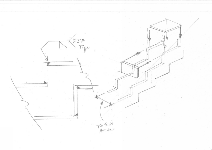
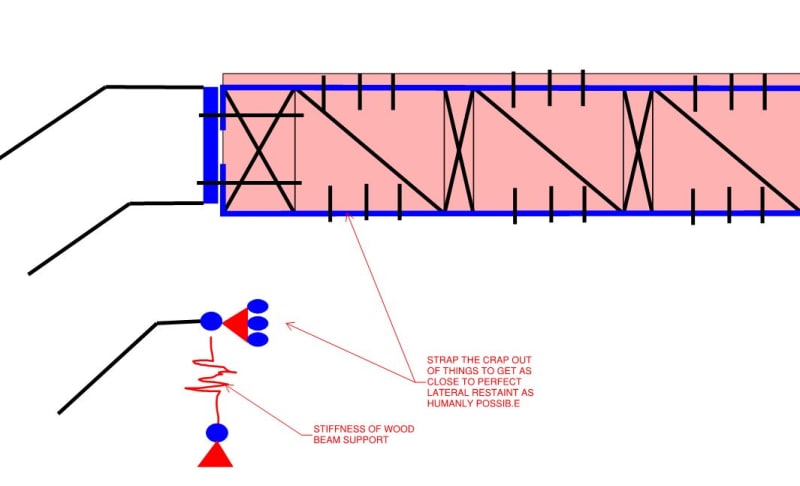
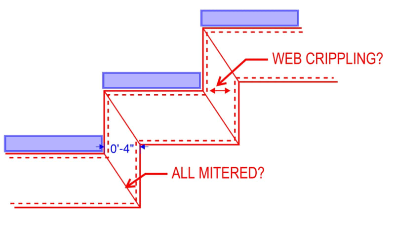
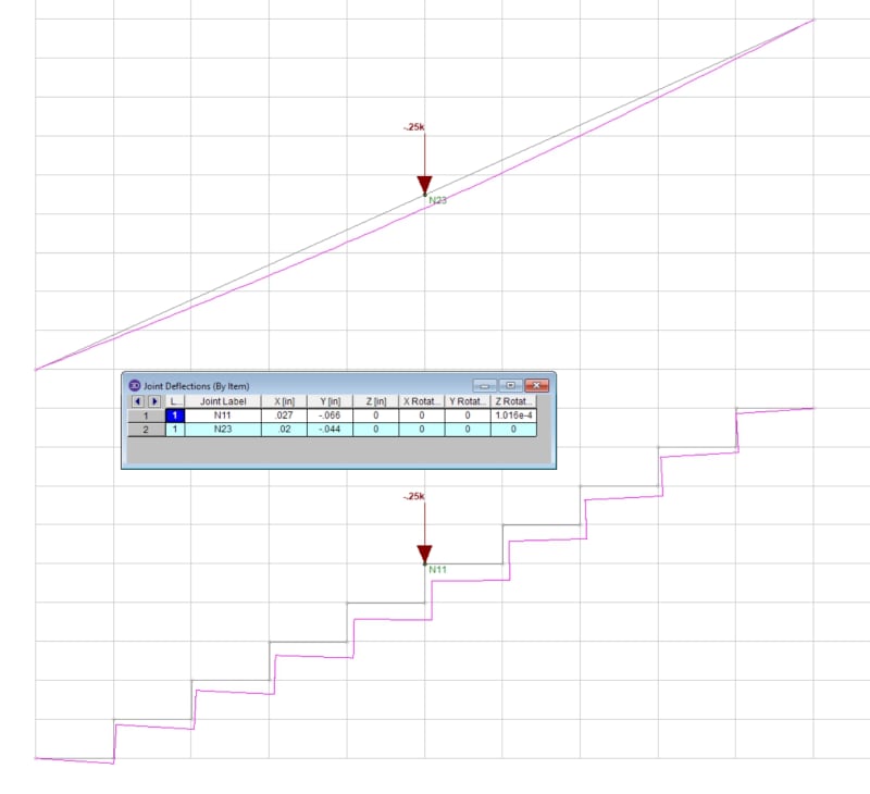
I have a client that wants to use hss tubes to create a stair stringer in a zig zag pattern spanning diagonally between two wood beams. Essentially, the tubes will follow the path of the risers and treads with hss6x2x1/4 horizontals, and hss4x2x1/4 verticals. They'll be two of these frames, with angles spanning between them for the tread attachments.

I've designed the hss members to have fixed connections at each of vertical/horizontal member intersections, but I'm a little uncertain on what type of weld should be used to achieve this. The steel will be exposed per the architect, so any exterior plated connections are off the table. If anyone has done something similar in the past, what kind of connection did you use? Any suggestions or thoughts are welcomed.
 
Replies continue below

Recommended for you

Being in Texas, I assume you are being required to meet the International Building Code. Your combination of members result in a riser height that greatly exceeds the code maximum. Your treads would have to be at least 3 inches thick to comply with code.

Further, this configuration is very labor intensive. You will need to use a single bevel on the open ends of the HSS being welded to a closed face of another HSS. You likely don't need a complete penetration weld, so partial pen is likely ok...but check stress levels.

 
HSS connections are their own animal when it comes to design. In addition to building code check out for some guidance.

Generally speaking it is much easier to do the design when the walls line up and the tube thicknesses are similar. But still you will have several pages of calculations to do.
 
I'm having trouble visualizing just how all that would fit together.
As I imagine it, it would look pretty slick if all those pieces were mitered to fit together. Or if ends are all cut square, it could look okay if those tubes had square outside corners, but they don't.
An alternate idea, cut zigzag shaped plates for the inner and outer faces, and weld flat bar between them to form top and bottom surfaces. Still a mess of welding little pieces, but might be easier to do it that way.
 
Ron - The lengths of each horizontal/vertical member will ensure code compliance for the tread depths and riser heights. Angles are welded to the inside faces of the tubes to create supports for the actual steps. I agree that the configuration would be very difficult to fabricate. I've already explained this to the client, but they insist this is what they want. I imagine that will change once they see the price tag later.

It would be nice if the corners were all mitered together, but that would be a nightmare for a fabricator I'd think. Bevel welds to the closed faces is what I was thinking, like Ron suggested. This is a high-end residential project, fairly short diagonal span, and the loads and stresses aren't high at all.
 
Seems like this will be a good candidate for the 'bouncy stair of the year' award. Probably fine for a private home - ask and ye shall receive.
 
Can you provide a sketch?
 
I think the basic is similar to design a concrete stair - utilize the bottom slab only. Though I would like to see more thoughts on stability of side sways.
 
The image shows a steel plate stringer, but what's been requested would be hss tubes. Not the banisters and railings.
 
Is there a reason that fillet welds would be objectionable? I'd normally only go with groove welds for the knuckle joints in the stringers.

As dold said, watch the vibration as that's where these things usually go wrong if they do. My wife did one that turned out to be resistant to fixing in the end. You could step on the intermediate landing with a moderate amount of force and the thing would swing laterally a couple of inches and then oscillate. That was single stringer though which is usually much worse for lateral stiffness. After a great deal of investigative work, we came to the conclusion that the issue was not actually the stair but, in large measure, it's wood beam supports and the connections to those wood beams. You'll see a lot of folks just treating those support connections as pins in their model. In a wood structure especially, that can be pretty far from the truth.
 
Interesting KootK - I have two stringers in this case with angles bracing them laterally. These stringers are attached to wood beams top and bottom. Both wood beams sit in "u" shaped saddles to steel columns on each side (they were coincidentally already on the plans for other reasons). I don't think this thing is going anywhere laterally. You raise a good point on the model connections though.

How did you end up correcting the issues with the vibration?
 
I think you shall focus on the stiffness of the stringers. Depending on the length of the stair, shear deformation may render all those intermediate braces ineffective, if the stringers are too flexible, and the treads are simply attached to them.
 
VTenge said:
How did you end up correcting the issues with the vibration?

We didn't. Failed remediation efforts included:

1) Welded in some supplemental horizontal bracing in the landing to stiffen that.

2) Drilled little holes and filled the HSS stinger with concrete.

4) Experimented with attaching some masses to the landing in various configurations.

Things to do with mass addition seemed to make it worse. I think that was because the real stiffness issue was with the weak axis bending of wood support beams. More mass on the stair proper wasn't really stiffening anything important but it was elongating the period which was making it more perceptible to humans.

dold's perception that it's less of a big deal in residential proved accurate. The owner just decided that he could live with it and wound up using it as an interesting conversation piece for his friends. To his credit, he viewed the trade off between the vibration issues and the awesome visual impact of the stair as a good value proposition.

I do homes for rich folks in Silicon Valley with some regularity and always worry that it will break the other way: me stuck in a serviceability related lawsuit against someone with a much, much greater capacity to hire quality legal help than I have.
 
Mitered corners would be messy. But if you use square corners you need to cap the end of the open HSS. For architecturally exposed steel, that will take a lot of work to get right. Both options suck and I don't think either will look great.

If they insist on the HSS look but don't want plate, I'd use plate anyway. Cut the stringer profile into (2) plates and join with riser/run plates. Now you're cutting your main member out of one piece, so weld distortion won't foul you up and fitting this up will be way easier. The weld joints in this configuration will be easier to clean up. Also, the most visible portion of the stringer, the exposed faces, are now solid plate instead of a mess of weld joints - will look 100x better. If they have money for it this is very feasible. I've worked on some of these custom plate stringers before and the end results can be very sharp.

PL_stringer_dsxflt.png
 
VTenge said:
You raise a good point on the model connections though.

I agree that you'll be in pretty good shape laterally for your setup. While you'll probably never know the the loads on your cross pieces -- or the stiffness benefit of them -- with any accuracy, the loads will be light as you said and their incidental moment connections to the stringers should form a healthy diaphragm.

As you know, most strucures work well as a result of good detailing rather than good calculation. For wood support, I do something like what I've shown below now. My wife's stair both lacked this kind of connection and had kind of a skinny bridge element for the floor diaphragms. Perfect storm of crud.

c01_jnapwx.jpg
 
OP, I'm sure you'll be fine strength wise in terms of the overall strength of the members/segments. But i'd keep an eye on local failure of the vertical HSS pieces. Gut check says web crippling might be worth a check where you have compressive stress concentrations at the joint where your toe would go if you're walking up the stair.

I like CANPRO's plate scheme much much better than using HSS. For strength, fabrication, and looks. I feel like HSS isn't going to look quite like they think it will after you consider how all of the corners/radiuses are going to get mitered. Seems like it would look weird.


Also keep in mind that you can't analyze it just like a straight stringer. Essentially your member is the total length of all the connected segments. Like if you had an accordion and 'unraveled' it. This would be important when checking stiffness.

ENGTIPS_ZIGSTAIR_rytumr.jpg

ENGTIPS_ZIGSTAIR2_rdweqs.jpg
 
I miss-understood what was meant by zig-zag. I thought it was just scissored. Definitely no fillet welds.

Accurate modelling would be very complex. Structurally, the top and bottom flanges of the your tubes will become pretty ineffective and you'll be left with the sidewalls acting like a pair of plates.
 
Could you justify plate stringers being braced by the treads? No welding except typical connections for stairs.
 
Status
Not open for further replies.

Part and Inventory Search

Sponsor