Follow along with the video below to see how to install our site as a web app on your home screen.
Note: This feature may not be available in some browsers.
sail3 said:the face of the HSS has no significant stiffness compared to the sides
Bones said:So my argument is not to worry about the HSS face bending because by then your shear lug is already gonna be having performance issues.
Bones said:If you use KootK's free body diagram and assume a narrow bearing width (maybe 2x wall thickness) at each the HSS walls parallel to the load, you could probably make a reasonable estimate of the bearing pressure on the surrounding grout and compare to an allowable.
Maybe I will design the lug for atleast this flexural behavior. I will use wl^2/12 and the HSS wall spanning 'D-2xt'. This should not be difficult to achieve.KootK said:If you're confident that you can get the grout in there you can, at best, split the load demand between the forward and rear HSS walls.
. Center of column/Center of lug at top of baseplate. That is top of shear lug.Why do you ask?KootK said:will you put your work point at mid height of the lug?
. I couldnt find any. Tried looking through all resources.bones206 said:Yea, I was thinking even while I typed that 2t was too conservative. Maybe there’s some testing out there that could shed some light on the performance of HSS shear lugs at ultimate strength levels. Maybe the stresses at the corners get happily redistributed or maybe the grout spalls away and the lug moves.
bones said:If I remember correctly, they would compare the peak bearing stress to the allowable bearing stress without any averaging or consideration of concrete crushing.
BAGW said:Why do you ask?
BAGW said:Dont we design the shear lug and the lug weld connection for that eccentricity? Assuming uniform bearing on the face of the lug and considering the moment arm from the center of the lug to attachment?
pg 244 said:Examination of the specimens after testing revealed that none of the shear lugs experienced any
noticeable deformations, and that the welds attaching the shear lug to the base plate all remained
intact. At the smaller deflections (less than 2% story drift), data from the string pots on the
column bases reveals no significant lateral movement of the column base (less than 0.04 in),
indicating that the shear lugs did indeed provide adequate lateral resistance to movement.
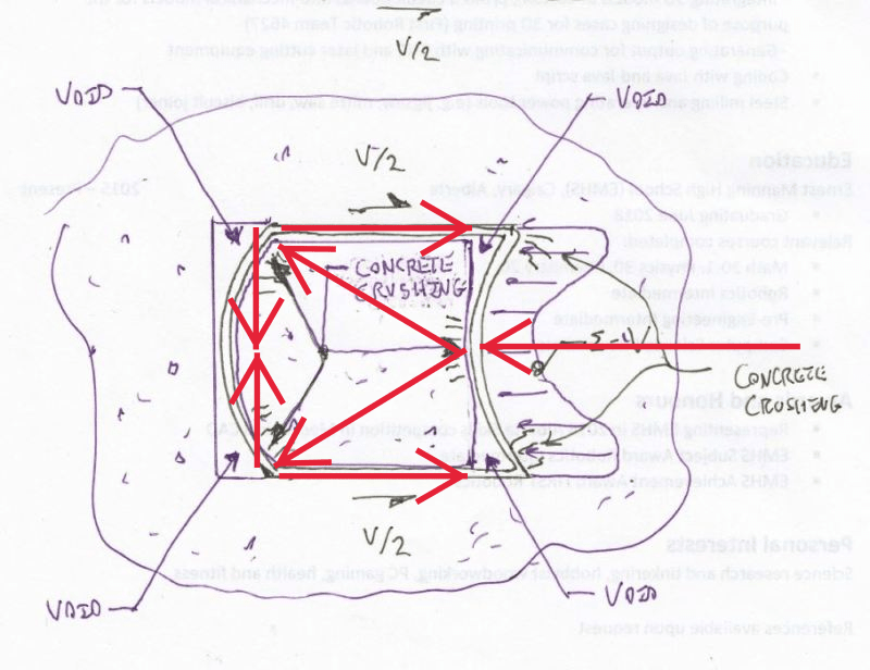
It wasn’t until the larger deformations (greater than 4% drift) that the shear lug became
ineffective. As noted previously, it was discovered in post-test analyses that there was a
significant amount of damage to the grout underneath the base plate and surrounding the shear
lug. At these higher deflections, the grout was crushed, removing any bearing surface for the
shear lug, and the shear lug became ineffective. Large lateral movements were observed at the
base of the column at the later end of the test cycles as the lateral resistance of the base shifted
from the shear lug to the anchor bolts.
BAGW said:can the gusset plate and weld between the gusset plate column and base plate be designed to take the moment due to eccentricity from shear instead of designing the column or the base plate for the eccentric shear moment?