ok, sounds less like school work, and the sketch is better.
first, there are lots of threads on scissor lifts, try reading them to get ideas.
second, review free body diagrams, then see how to apply them to the problem. some clues ...
1) break the problem into three pieces, the three different members; as well as looking at the structure completely as a free body (ie what ground reactions will react the applied load).
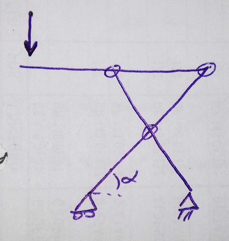
2) consider the top beam. one (the RH one) joint is almost certainly hard located (fixed in position, at the end of the beam) but the LH will slide along the beam. this is not quite as you've shown. this has implications for the reactions on the LH support.
3) the top beam will solve without moments at the supports. It is hard to see how a practical structure would have moments (I'd expect to see pins at these locations).
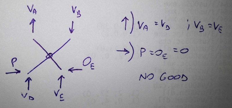
4) then consider each arm as a free body. Start with the one with the actuator load applied. You have to determine the load at the middle joint, that passes from one inclined member to the other. I think you know the other loads on this member.
third, an important detail ... you mention the actuator, Does it attach to the opposite leg or to the ground ? If the ground, the problem just became indeterminate again (maybe) ! Though you may be able to figure the actuator load from the work done.
another day in paradise, or is paradise one day closer ?