Tek-Tips is the largest IT community on the Internet today!

Members share and learn making Tek-Tips Forums the best source of peer-reviewed technical information on the Internet!

  • Congratulations MintJulep on being selected by the Eng-Tips community for having the most helpful posts in the forums last week. Way to Go!

How to make side edges smoothly blended together?

  • Thread starter Thread starter giangnguyen
  • Start date Start date
G

giangnguyen

Guest
Hi everyone,

From this thread: http://www.3dcadforums.com/threads/3742-How-to-close-a-wingtip.

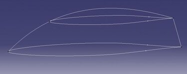
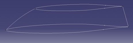
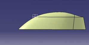
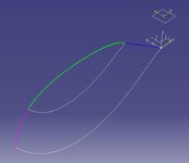
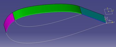
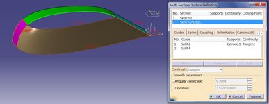
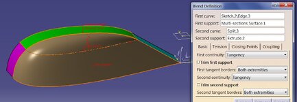
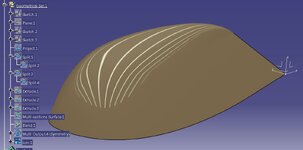
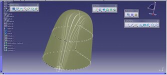
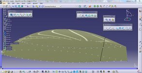
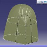
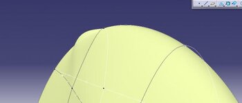
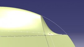
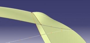
A wingtip closing has been discussed. However, I note that by using "blend" function, the rounded region is essentially a circle shape. Meanwhile in real car, it seems that the rounded region does not look like a circular shape.

For example: https://scientificgems.files.wordpress.com/2015/10/1_nuon.jpg.

Or you can search images on google: Nuon 2015

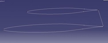
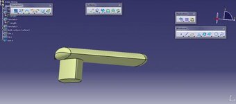
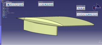
I attach here my file for your reference. https://www.dropbox.com/s/3jpinis264anxgn/Main wing to ask.CATPart?dl=0

So I would like to ask if you know any method else to solve this problem. From aerodynamic point of view, it is not good if things change suddenly, so it is usually better if things change gradually by rounding.

Thank you very much.
 
Add a series of Planes along the length of the fuselage, then add a sketch at each plane of the profile shape you want at each section (with the curve starting and stopping tangent to the fuselage surface). Then make a Multi-Section Surface passing through the section curves with the edges of the fuselage as guide curves.
 
Dear MrCATIA,

I have tried both, the difficult section is at the nose or tail. For the Multisection option, it appear the error "the extrusion of a vertex of the profile leads to a cusp" and the formed surface is distorted.

For the "Fill option", it rapidly comes close to the side surface, very difficult to formed a nice, smooth transition to the center's rounding surface. Or it can be distorted convexly.

I attach here the files and picture for your reference. Here is my rounding for the cockpit, for the mainwing, it is similar, they are both airfoil shape.
https://www.dropbox.com/s/4oqg1gvi5w1fcin/Spline connecting to form a top curve 2.CATPart?dl=0
https://www.dropbox.com/s/0gzqb36ouldvkin/Spline connecting to form a top curve 3.CATPart?dl=0
https://www.dropbox.com/s/tuaw59lkr87abpg/Spline connecting to form a top curve 4.CATPart?dl=0
 

Attachments

  • distorted LE.jpg
    distorted LE.jpg
    9.9 KB · Views: 7
  • distorted TE 2.jpg
    distorted TE 2.jpg
    8.5 KB · Views: 6
  • distorted TE.jpg
    distorted TE.jpg
    10.6 KB · Views: 6
Do you have a CATIA instructor or someone who can sitdown and work with you to show you?

Surface modeling is not easy, especially with aerodynamic shapes.

I don't understand the attached pictures #1 and #3. Picture #2 looks like a Fill surface that doesn't have supports to define continuity.

I don't like to download files onto my employers computer, and I had problems in the past with Dropbox so I'm definitely not using that again. I'm sorry I can't provide the step-by-step, detailed help that you need.
 
Last edited:
Dear Mr. CATIA,

Unfortunately that I am the first one in my school using CATIA. :( The only official document I have is CATIA documentation, and other things are google and youtube.

Picture 1 and 3 is "Fill" with support, picture 2 is "Fill" without support, as you can see the support line in picture 2.

Thak you very much for your care. Do you mind if I upload to something like mediafire or googledrive?
 
Dear MrCATIA,

It looks similar to this video, from 39:53 to 40:38, within less than 1 minutes, but I do not know how did he do.. He started with distorted "fill" like me, but somehow he adjusted something.
https://www.youtube.com/watch?v=TzyTY0440U8
 
In the video above, he modified the Fill surface by adding/removing the support surfaces until he was happy with the results. But his result is not that good.

I would try a Multi-Section Surface based on the two edge curves and the adjacent surfaces for tangency supports. But I would also add a guide curve in the center to help control the shape of the surface. This might not be that good either, but it's the next thing I would try.
 
Please attach a picture of what you are working on.

I do not download files.
 
Dear MrCATIA,

Let's say I am constructing the canopy by sections of top airfoil and bottom airfoil like the 1st picture.

Then I want to build the whole canopy with rounded top for aerodynamics reasons. It skeleton is like the 2nd picture. But I do not know how to build surfaces to fit this skeleton.

The real things in life is like the 3rd picture.

I have temporary solution is to split the vertical spline into 2 parts, hide the top one, and use "blend" to round it. Like the 4th and 5th picture. However, it is not so smooth transition at the contact point of "blended" surface and the original vertical splines, as you can guess, because "blend" is essentially forming a circular cross section, the 6th picture.

The real thing is so smooth and nice. Could you tell me how can I draw like this? The final picture.

Since it is over size upload allowed, I upload it to my google drive, picture numbered from 1 to 7.
https://drive.google.com/open?id=0B8Ha0eSsJsuHQkJXdW0zUXRRd28

Thank you very much.
 

Attachments

  • 1.jpg
    1.jpg
    8.9 KB · Views: 4
  • 2.jpg
    2.jpg
    10 KB · Views: 4
  • 3.jpg
    3.jpg
    25.3 KB · Views: 3
  • 4.jpg
    4.jpg
    8.3 KB · Views: 3
  • 5.jpg
    5.jpg
    8.7 KB · Views: 5
Dear MrCATIA,

Could you help me this rounding problem?
 
Sorry for the delay. I had a little free time to work on this canopy, and started by creating my own model based on the fourth picture above.

When working with symmetrical surfaces like this, I like to model one half only and then mirror the results to get the other side. So, I started with two half curves in the horizontal planes, imposing tangencies at each end. I added the center curve (in the vertical plane), and then Split it into 3 sections.
View attachment 1715

Then I Extruded each of the 3 section curves (in Y-direction) to get support surfaces.
View attachment 1716

I added a Multi-Section Surface for the bottom half, using 2 Guide curves and only one Support surface, and the Z-axis as the Spine.
View attachment 1717

For the top surface, I tried a Fill surface and a Blend surface (with support surfaces on both), and thought the results were the same. I kept the Blend and deleted the Fill.
View attachment 1718

To finish, I hide everything except for the two surfaces. Then Symmetry (mirror) the two surfaces to get the other side, and Join all 4 surfaces into one. For a quick check, I changed the Lighting to the Neon option to look for surface quality. Wasn't happy with the tail section, so went back to the original sketches and adjusted the tangent angle. Here's my finished result:
View attachment 1719
 

Attachments

  • canopy2.JPG
    canopy2.JPG
    30.1 KB · Views: 7
  • canopy3.JPG
    canopy3.JPG
    36.7 KB · Views: 6
  • canopy4.JPG
    canopy4.JPG
    109.4 KB · Views: 8
  • canopy5.JPG
    canopy5.JPG
    90.9 KB · Views: 7
  • canopy6.JPG
    canopy6.JPG
    78.7 KB · Views: 8
Last edited:
Dear MrCATIA,

I do not know how to say for your effort. You are a great enthusiastic teacher.
 
Dear MrCATIA,

Perhaps my previous failure is that I do not know how to form artificially the extrusion plane to make it as supporting surface as you; instead, I use directly two multi-section surfaces of opposite side, then Blend them. The results shape is not as nice as the one formed by your method.


By the way, I use Neon Lighting as you suggested to check the surface. But I do not know how good/ bad it is. So I attach its pictures here, could you please give me some comments how to evaluate surface quality?

Thank you very much.
 

Attachments

  • Neong lighting LE.jpg
    Neong lighting LE.jpg
    21.4 KB · Views: 2
  • Neon lighting 2.jpg
    Neon lighting 2.jpg
    23.7 KB · Views: 2
  • Neon lighting TE.jpg
    Neon lighting TE.jpg
    9 KB · Views: 3
Dear MrCATIA,

Can I ask you a small question more?

As I read from some sources, rounding side edges of an airfoil is to deal better with side wind. And I do it for my case by BLEND function as you suggested. However, it is quite crude. I attach here 2 pictures from my drawing.

The disadvantage of rounding is that it exposes more wetted area, which in turns leads to more drag. Around the middle of the wheel fairing is the driver with canopy, so it already has something to block side wind; therefore, there is no need/ or very little to rounding to save wetted area.

Like these pictures from other ones, you will see that there is almost no rounding around the driver, unlike my case.

http://img.rtvoost.nl/T3/252178.jpg
http://news.europawire.eu/wp-conten...estone-World-Solar-Challenge-in-Australia.jpg
http://dailyscene.com/wp-content/uploads/solar2-640x359.jpg

Their designs are really elegant.

Actually, the wheel fairing where a driver sits is actually formed by vertically translation of an airfoil parallel to ground.

I guess that it is still the same BLEND function, but it should be multi-blend rather than single blend like what I do. I have thought for a long time but I still do not understand how did they do this, and around me there is no people using CATIA to ask.

So could you give me some suggestions?

Thank you very much.
 

Attachments

  • crude rounding 2.jpg
    crude rounding 2.jpg
    14.5 KB · Views: 5
  • crude rounding.jpg
    crude rounding.jpg
    18 KB · Views: 5
Dear MrCATIA,

Perhaps my previous failure is that I do not know how to form artificially the extrusion plane to make it as supporting surface as you; instead, I use directly two multi-section surfaces of opposite side, then Blend them. The results shape is not as nice as the one formed by your method.


By the way, I use Neon Lighting as you suggested to check the surface. But I do not know how good/ bad it is. So I attach its pictures here, could you please give me some comments how to evaluate surface quality?

Thank you very much.

This is a really good question Giang! I think it's so good, that I copied it to a brand new thread. http://www.3dcadforums.com/threads/8493-How-to-evaluate-surface-quality?p=24224#post24224
 
Please show off some big size picture that you're working then somebody here will help. I also don't see the picture clearly
 
If you click on the picture, it will open bigger in a new window
 
To model the longitudinal beams I created a catalogue using a design table with the overall beam length increasing in increments.
 

Part and Inventory Search

Sponsor

Back
Top