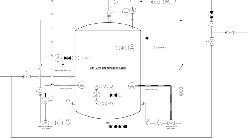
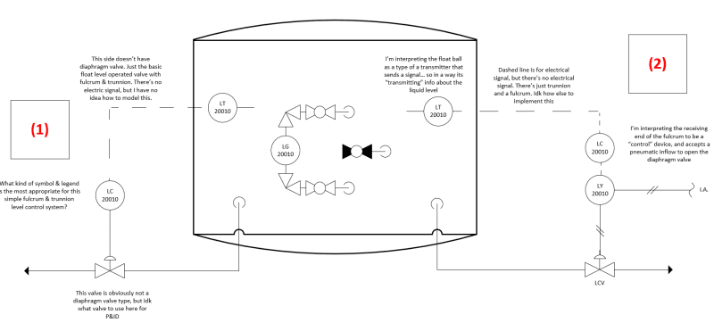
I need to model the existing oil and gas upstream facility in P&ID. For now I'm focusing on the vertical 2-phase separator's liquid control system.
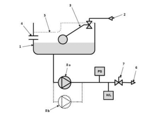
The separator has two liquid dump sides, one is usually closed and the other is usually open, but I still need to model both of them in P&ID. Both sides have a floating ball inside the vessel that detects a liquid level, which is connected to the trunnion, and then the receiving fulcrum. The difference is that one is a (1) lever operated, while the other is (2) pneumatic-operated type.
I came up with some preliminary P&ID for the liquid control portion of the 2-ph vertical separator (attached image). I know that this is massively wrong, so I'm looking for feedback.
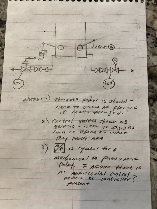
Q1. To my understanding, the T (transmitter) in P&ID is intended for devices that send electric signals. The way I modeled seems to be wrong because there's no electric line that sends liquid level information. But I don't know how else to connect the floating ball + fulcrum combo to the actual control valve. What should I do?
Q2. On the (1) side with a lever operated valve, I'm not sure what symbol I should use. I used diaphragm-type symbol for both sides, but I think the lever-operated side should be using a different symbol. Any recommendations?
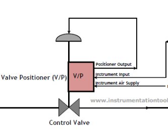
Q3. On the (2) side with the pneumatic-operated valve, I'm not sure if I can use the LC + LY combo for the pneumatic system. I used LC+LY combo because that's what I commonly see on P&ID examples I found from other people, not sure if its applicable in my case too
Any advice is appreciated, I'm really trying to learn the details whenever possible. I have no mentor to teach me this other than here.
++ the (1) lever-operated side looks exactly the same as this Kimray video I found:
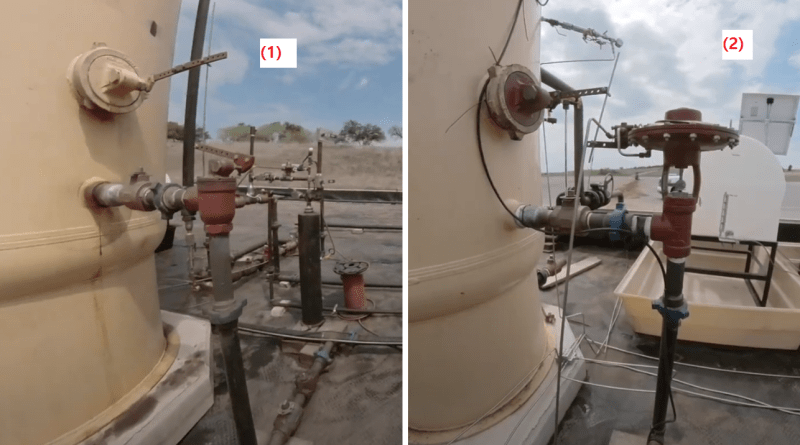
The separator has two liquid dump sides, one is usually closed and the other is usually open, but I still need to model both of them in P&ID. Both sides have a floating ball inside the vessel that detects a liquid level, which is connected to the trunnion, and then the receiving fulcrum. The difference is that one is a (1) lever operated, while the other is (2) pneumatic-operated type.
I came up with some preliminary P&ID for the liquid control portion of the 2-ph vertical separator (attached image). I know that this is massively wrong, so I'm looking for feedback.
Q1. To my understanding, the T (transmitter) in P&ID is intended for devices that send electric signals. The way I modeled seems to be wrong because there's no electric line that sends liquid level information. But I don't know how else to connect the floating ball + fulcrum combo to the actual control valve. What should I do?
Q2. On the (1) side with a lever operated valve, I'm not sure what symbol I should use. I used diaphragm-type symbol for both sides, but I think the lever-operated side should be using a different symbol. Any recommendations?
Q3. On the (2) side with the pneumatic-operated valve, I'm not sure if I can use the LC + LY combo for the pneumatic system. I used LC+LY combo because that's what I commonly see on P&ID examples I found from other people, not sure if its applicable in my case too
Any advice is appreciated, I'm really trying to learn the details whenever possible. I have no mentor to teach me this other than here.
++ the (1) lever-operated side looks exactly the same as this Kimray video I found: