Hey KootK
KootK said:
You do show up with the wackiest truss profiles. It makes for interesting problem solving
Hahaha,… I’ll take that as an acknowledgement of my design creativity when faced with impossible constraints.
Yep, I get responses similar to that a lot; most problems are easily solved with traditional approaches; however, what everybody else gets to see are the difficult problems.
KootK said:
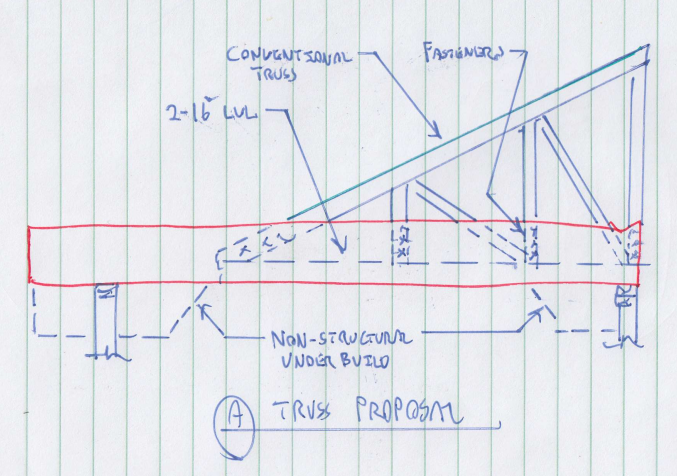
Convince the building architectural designer to choose his roof and ceiling planes such that you have conventional truss profiles.
The roof profile is a traditional hip roof with gables over bay windows along with simple pan ceiling profile
KootK said:
…while all truss profiles may well be possible, that does not necessarily mean that they are all advisable in my opinion.
Perhaps true; however, when traditional truss profiles fall short more creative approaches should be examined and adopted when applicable.
KootK said:
What you've got going on between G&H makes me shudder
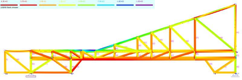
Yep, the bending at G & H was one of the top concerns; however, the stresses were well within the capacity of the beam specified. The real issue arose from the tension in the bottom chord and here I had to scab a 2x8 to meet the load requirement and this is evident when examining the beam stress plot.
KootK said:
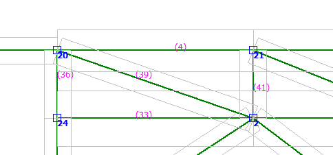
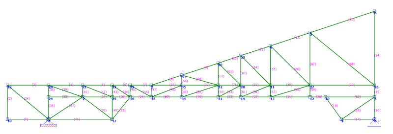
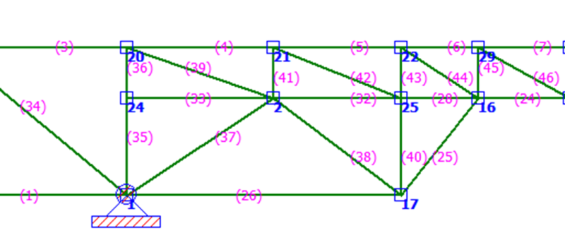
The diagonal loads (members 25 & 26) are probably carrying non-trivial loads because, to the left of Z (node 16), those members are becoming the bottom chord effectively.
Actually, I’ll have to go with the numbers from the analysis program which indicates otherwise. (Yeah, yeah,… I know, not fair, you didn’t have access to the numbers.) Anyway, consider horizontal tensile loads from node 16 to the vertical support beams 35 & 36.
Bottom Chord
#28 2310 Lbs Tension
#32 651 Lbs Tension
#33 307 Lbs Tension
#39 978 Lbs Tension at 22 degrees (906 Lbs Horz)
#42 1079 Lbs Tension at 22 degrees (1000 Lbs Horz)
#44 896 Lbs Tension at 35 degrees (734 Lbs Horz)
#41 & #43 are in compression
Total tensile load in or transferred from Bottom Chord = 5,908 Lbs
Diagonal Member
#25 1614 Lbs Tension at 53 degrees (962 Lbs Horz)
#26 809 Lbs Tension
#38 312 Lbs Tension at 45 degrees (220 Lbs horz)
#37 & #40 are in compression.
Total tensile load transferred from Bottom Chord = 1,991 Lbs
The tensile load in the bottom chord is just shy of 3 times the load transferred by the diagonal members. So, I would say the bottom chord clearly functions as a bottom chord from one support to the other support.
KootK said:
Localized, nailed connections tend not to possess a great deal of rotational stiffness. Nail slip etc.
KootK said:
I think that you'd get a more convincing moment connection with the tooth plates unless the extents of your plywood gusset will be very large.
Actually, I would think the rotational stiffness of any connection has a direct correlation to the moment-arm of the connector. From what I have observed manufactured trusses have very small metal plate connectors thus yielding very small moment-arms. Where plywood gussets tend to be much larger and consequently have a much greater moment-arm. By having a greater moment-arm the stresses on the nails most distant from the node is much less than the stresses seen on the connector plates at their extremities. With higher moment stresses on the metal plates I would expect to observe tooth slippage along with thin plate buckling. Actually, I really would like to see a comparative study between plywood gussets and metal plate connectors; if anybody is aware of one could you please share the link. I would think this type of study has been done at one time or other.
KootK said:
Your design effort will be greatly reduced if you go with the standard assumption of pin ended web members.
I actually wrote my own truss analysis program; and, I limited the scope to only pin connections. My program compared favorably to the professional analysis program; however, when I started to consider moments in the frame I was surprised to see that members that passed in my program failed in the professional program. Why,… because of the buckling stresses that developed in the beams which I had not accounted for. This caused me concern and when considering the type of gussets I planned to use (glued and nailed) which would transmit moments I elected to use moments in the design. Actually, the design effort to include moments in the truss design is trivial. The real concern is the increased material necessary to handle some of the buckling stresses. In other words increased cost.
Thanks for the sketch. I really appreciate your effort. However, “I don’t love your truss”, hahaha Just kidding Koot.
Although, in all sincerity I am uncomfortable about the side-saddle truss and the eccentric loads it induces and I have never been fond of drilling into beams. With that set aside I can see incorporating some of your ideas.
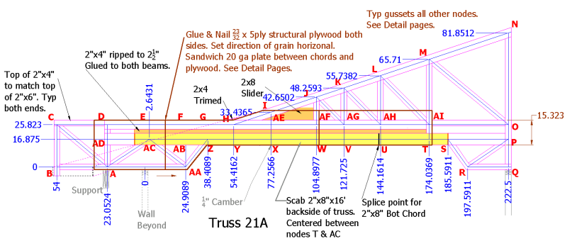
If you will note in my design, that when I the remove of the diagonal members between the chords and then place the ripped 2x4 between the chords I effectively create a 2x16 LVL; ie, (2x8 + 2x6 + 2x2.5 all glued and nailed together) All I have to do is extend the 2x2.5 member to the support ends. The reason this was not extended originally is because the loading on the ends didn’t warrant it. One area of slight concern is building up the support on the left side. Several trusses sit on top of a double 2x12 which spans 10’ or so and there could be some lateral stability issues that need to be examined.
I do like the concept of removing the loads off the ceiling framing; although, as shown it would suggest toe nailing which may not be adequate for ceiling loads. So gusset plate and a diagonal member may be appropriate.
I would really feel much more comfortable if the conventional truss were set on top of the beam and attached with gusset plates. This would make the design much simpler by determining the point loading from the conventional truss and then apply those point loads to the design loads of the beam.
Finally, with the modifications mentioned, I really don’t see any significant change in the fundamental design so
I will probably still have to scab a 2x8 on the bottom of the beam to handle the tensile load. This will be determined by the truss analysis program.
Your rebuttal.
![[thumbsup2]](/data/assets/smilies/thumbsup2.gif "[thumbsup2] [thumbsup2]")