Continue to Site

Eng-Tips is the largest engineering community on the Internet

Intelligent Work Forums for Engineering Professionals

  • Congratulations waross on being selected by the Eng-Tips community for having the most helpful posts in the forums last week. Way to Go!

How to Combine Wind Loads On Roof? (ASCE 7-16, Directional Method)

Status
Not open for further replies.

composites_guy

Mechanical
Dec 2, 2020
7
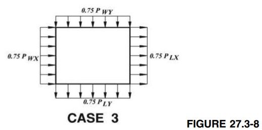
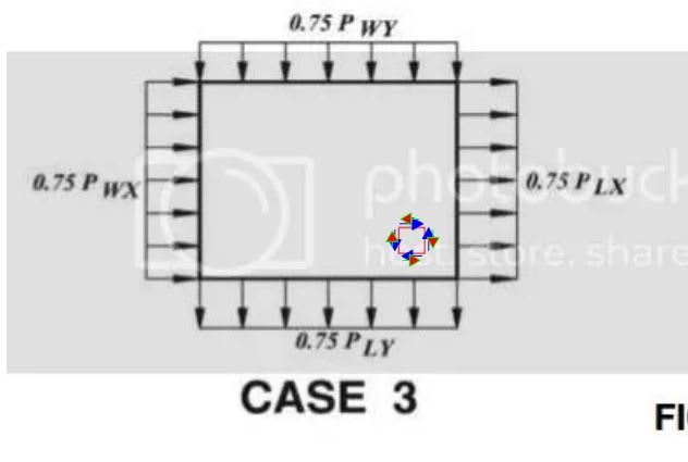
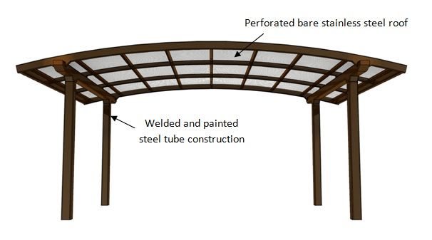
The following question regarding wind load combinations has come up a couple of times before on this forum, but I haven't found a complete answer. Reference the figure below.

case3.jpg


Question = How do you handle the summation of loads on the roof?

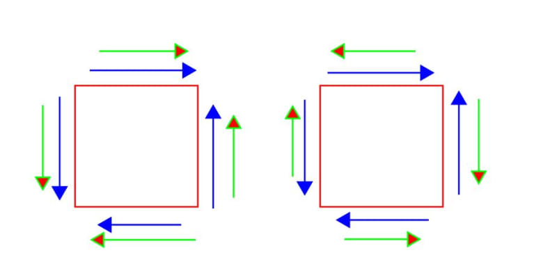
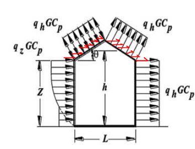
A quick recap: Previous posts point out that all combinations of wind loads from different directions must be considered, resulting in several separate wind load cases. That makes sense, and treatment of the horizontal forces on the walls seems straight forward. Previous posts have also pointed out that the wind loads on the roof (for a given wind direction) typically have a positive and negative load case, with differing pressures on the windward and leeward half of the roof. What isn't clear to me is how you handle the roof summation for a given pair of wind directions and say the "net pressure pressure" case from each direction. Do you break there roof into sections (quarters) and sum the pressure in each section?
 
Replies continue below

Recommended for you

The two, orthogonal loading directions will each produce their own shear demand in the diaphragm. Those shear demands should be added together keeping in mind that:

1) Where both, opposite side shear demands are CCW, they need to be added.

2) Where both, opposite side shear demands are CW, they need to be added.

3) Where one shear demand is CW and the other is CCW, they can be subtracted. This simply won't be a governing condition.

I find it helpful to do little differential sheathing panel element diagrams like those shown below.

In the interest of truthiness, I've not yet seen an engineer go to the level of detail in diaphragm design that we're discussing here.

C01_yezjzc.jpg
 
In case it wasn't clear what I was alluding to...

C01_pl4mml.jpg
 
So... do you break the roof into sections and apply this process? (Such that the sum of loads is evaluated for each location on the roof)?

I have to be honest, this is my first time through the code and its not immediately obvious that this figure is even talking about roof loads.
 
OP said:
So... do you break the roof into sections and apply this process? (Such that the sum of loads is evaluated for each location on the roof)?

I don't think so but it's hard for me to tell as I'm not sure that I understand the approach that you're suggesting. With the vertical lateral force resisting elements (bracing) placed at the perimeter of a rectangular shaped building, we typically treat the diaphragm as a simple spanning beam in each of the two directions.

I recommend developing a particular load case and bracing scheme that you'd like to study and then posting that here. That way, we can work through the example together and, hopefully, iron out any questions that you have.

OP said:
I have to be honest, this is my first time through the code and its not immediately obvious that this figure is even talking about roof loads.

It appears to be talking about wind loads applied to the walls of a building. Of course, at the upper level of the building, it is the roof deck that laterally supports the tops of the walls. So, in that sense, the figure is talking about uniformly applied wall loads (PSF) that will be aggregated into lateral line loads (PLF) at the perimeter of the deck.
 
I could be way off here, but I don't think he's asking about the diaphragm, KootK. I think he's wondering what roof pressures to apply concurrently with the wall pressures.

These cases are intended to determine the load to be resisted by the main wind force resisting system - shear walls, braced panels, braced frames, moment frames, etc. and diaphragms - so we don't care about the VERTICAL force in this case. The description of Case 1 and Case 2 states "design wind pressure acting on the PROJECTED area perpendicular to each principal axis of the structure". Case 3 and 4 then reference 1 and 2, so the same concept applies. So using Figure 27.3-1 (C.p), we see that you would apply the horizontal component of the windward and leeward pressures with the windward and leeward wall pressures.

windonroof_pananj.jpg


If it were a flat roof, there would be no contribution. If you have parapets or mechanical equipment, you'd need to include those in the appropriate directions.
 
PhamENG is exactly correct when he said " I think he's wondering what roof pressures to apply concurrently with the wall pressures."


I guess that I should be more specific on what I'm trying to do. I'm designing a pergola for my back yard (pictured below). I'm a structural analyst in the aerospace industry, so my analysis method is one that is familiar to my day job... but I am not trained in civil/structural building design. I built a 3D finite element model of the structure (every nook and cranny modelled) and am trying to get wind pressure loads to apply to it, for use with an allowable stress design approach. I've used both the flat-monoslope wind calcs (theta = 0) and pitched roof wind calcs (theta = 7 deg) from ASCE 7-16 Chapter 27 to estimate loads since my roof is curved but nearly flat. Horizontal loads are the minimum 16lb/ft^2 design load from ASCE 7-16 27.1.5 applied to the frontal area of the pergola. I was planning to apply the wind loads to the model roof and "wall" frontal area simultaneously with dead and live loads (per the load combinations in ASCE 7-16 24.1) in several separate load cases. Now I'm asking how to combine wind load from different directions on the model.

Pergola.jpg
 
For that, I'd keep it very simple. Run a 0 degree and a 90 degree, and then combine the resultant stresses/forces in the members. In other words, if 0 degree induces 2kips in leg A and 90 degree induces .5kips, I'd check 0.75*2+0.75*0.5.
 
In a structure like this the highest stresses will be in the welds at the top of the vertical posts, or in the welds where the roof's arc-shaped beams meet their support. Stress is not a simple scalar that can be extracted at the high stress locations for each load case, and squared and summed in a hand calculation. Its a tensor that must be properly combined at the location of interest for the two load cases, and then turned into something useful (Von-Mises stress, or the stress components on the weld throat for instance). You have given me an idea though. I can run each case (0 degree wind, 90 degree wind, live load, dead load, etc) separately and use the finite element tool to produce various combinations of the results. That would be speedy too since the computer wouldn't need to recalculate the full solution for each load combination. However, since this would involve linear combinations of solution results it would limit me to linear elastic, small-deformation theory. That would be fine for this pergola, but it looks to me that the steel code AISC 360 Appendix A requires large deformation theory.

So... I'm back to wondering how to define separate wind load cases on the model.
 
Well...if you're going to design this like an airplane...I can't really help. How big is this going to be? Unless you're hosting 150 of your closest friends under it, I have a feeling that the final design result you get from my suggestion will be rather close to the more nuanced and, yes, accurate approach you want.


I checked the code and AISC 360 Appendix A only requires 2nd order deformation effects "as appropriate" to the structure... so not necessary here I don't think. That means that I could look at combinations of linear elastic solutions, which is probably the direction that I'll head (unless someone else has thoughts on the figure in the original post).

The pergola is approximately 21' x 15', which is just big enough for my local town to require a building permit and structural report.
 
Wind loads on a roof... I can feel my blood pressure rising.

Is it really a roof if the diaphragm is made out of perforated metal?
 
CrabbyT - yes, it would absolutely be a roof. How well the perforated steel acts as a diaphragm would certainly be a good question. For a fully welded tube steel structure, though, I'm thinking a diaphragm probably isn't going to be all that important.
 
Why are you bothering to design this if you need a structural engineer to stamp drawings? This is a very simple structure that you seem to want to make very complicated. The EOR that has design responsibility will conduct his own calcs.
 
We're engineers right? I do it because I enjoy it:) It is unclear that I need a stamp on this pergola. My town's building department told me they'd accept my analysis as an owner/builder, but they would review it thoroughly.

I'm not a structural engineer looking at buildings every day so I don't tend to think in terms of diaphragms, shear walls and the like. To me it is just another structure that needs to take some loads. I'm happy to learn what I can though about your end of the industry, and appreciate your comments. I've read through several of your codes for this project (ASCE 7, IBC, AISC 360, ACI 318). My Ph.D. and work experience is more along the lines of a general purpose structural analyst (race cars, speedboats, airplanes, missiles, factory cranes and stands, etc.)

The tubular steel frame for the pergola is quite stout. The beefy size is more aesthetic than structurally necessary. Its gotta be pretty since it is for my wife:) I've already done some preliminary analysis and I can toss just about any combination of the ASCE 7 loads at it and have plenty of margin. My question about the roof wind combinations comes because I don't want to turn in something that's out of keeping with your best practices.
 
In that case I don't see the confusion as noted in ASCE 7-16 case 3 is simply 75% of the windward and leeward wind pressures acting simultaneously in both orthogonal directions. If you're turning this into some intellectual exercise your roof slope appears to be less than 5 degrees so you'd add parapet wind load to the fascia. Actually maybe you should design this project per Chapter 31...

You don't state where you live but as this is a small residential project the reviewer will likely not even be an engineer. If it is an engineer he'll likely be more interested in making sure your detailing isn't crazy and that you have some reasonable footings and anchorage/embed.

What do I know though I don't design racecars...
 
Harbringer, thank you for the reply. If you know about wind loads on building's that's better than me;-)

So, are you thinking that Case 3, on my structure, would ignore roof loading (or a least the vertical component of the roof load)?
 
What specifically do you mean by roof loading?

If you are talking about dead load then using ASD load factors you would use 0.6 time the resisting dead load for uplift and overturning(0.6D+0.6W).

If by roof loading you mean the wind load on the roof, Cn from Fig 27.3-4 is your net pressure coefficient which includes contributions from the top and bottom surfaces of the roof. This is all to be applied to the lateral force resisting system components (in your case it appears to be a series of cantilever columns). I would also ignore diaphragm action from the panels and check the edge beam weak axis for the OOP wind loads combined with full dead load (D+0.6W Chapter 2).

For components such as the panel attachments this would be designed for C&C wind loads from Chapter 30.

This is an open structure correct? No walls. If so then the only wind load is due to the roof. No structural engineer I know would calc the wind load on those columns.
 
Similar to PhamEng's first reply, I also do not apply the Case 3 combination to the vertical component of roof pressures.

For vertical pressures, I only consider the higher value of the two orthogonal directions (case 1a and 1b).

For horizontal pressures (walls, parapet, or component due to roof slope), I do consider directional cases 1-4 as appropriate.

----
just call me Lo.
 
Status
Not open for further replies.

Part and Inventory Search

Sponsor