Hi Bill, Keith, CompositePro, and Muthu,
Thank you for your continued support. The suggestions of using a clutch or other "loose" or "slippy" drive mechanism makes total sense to me if given my 60:1 gearbox reduction and my roll diameter, I was running the motor at a speed that (without slipping) resulted in the roll surface speed being faster than my web speed. This is not the case (and I apologize for not adequately explaining my application). As I believe Keith and Compositepro alluded to, if I insist on using the gearbox, I would have to implement a drive system with some type of closed-loop, master/follower, electronic gearing type speed controls. I believe this is exactly what I am doing. I will try to explain using my original illustration, which I have pasted again below...
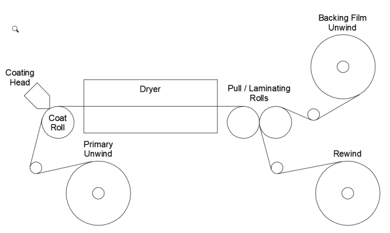
...I actually have two separate drive systems with closed-loop speed controls, one for the Pull/Laminating Rolls and one for the Coat Roll. As it is the Pull/Laminating Rolls that determine web speed, I configure the Pull/Laminating Roll Drive System as the "Master" Drive. The Pull/Laminating Roll Drive System consists of a DC motor fitted with a 60 PPR ring-kit along with a DC regenerative drive board and a closed-loop speed controller. The speed controller allows operators to enter a speed set point in feet/minute. Internally, the speed controller does some scaling using roll diameter, gear reduction, and ring-kit PPR to relate ft/min to motor RPM, but the end result is that it controls motor RPM so that the actual roll surface speed will equal the entered set-point. As long as the gap between the two Pull/Laminating Rolls is set properly so that there is no web slippage, this ensures that my web speed will be the same as the entered speed set point.
Just like the Pull/Laminating Roll Drive System, the Coat Roll Drive System consists of a DC motor fitted with a 60 PPR ring-kit along with a DC regenerative drive board and a closed-loop speed controller. The only difference is that I configure the Coat Roll Drive System as a "Follower" Drive. In this configuration, the Coat Roll speed controller allows the operators to enter a speed set point as a ratio of the Pull/Laminating Roll speed. Typically this is always 1:1 because while the Pull/Laminating Rolls actually determine web speed, we just want to match the surface speed of the Coat Roll to the web speed so as not to create drag. (Sometimes we might adjust this to 0.999:1 or 1.001:1 just to compensate for any stretching or shrinking that might happen in the dryer). Internally, the Coat Roll speed controller monitors the feedback not only from the Coat Roll motor, but also the master feedback from the Pull/Laminating Roll motor, and (doing the necessary scaling), controls Coat Roll motor RPM to achieve the desired speed match.
Anyway, this control scheme works fine. I have absolutely no problem getting the speeds to match using this type of drive system with gearboxes. I have gotten this to work many times with different gearbox ratios, sometimes with an additional belt/pulley reduction in addition to the gearbox reduction. I choose my gearbox and belt-pulley reduction based on the particular customer's required speed range.
The reason I originally posted this question is because I strongly suspect that I routinely over-size the motors I use because I do not know how to calculate required motor horsepower based on what I am asking the motors to do.
Just to complete the description of my application, Muthu touched on the fact that this application sounds similar to a cassette recorder where the tape has to travel at a constant speed, but the Unwind and Rewind spools have to vary in speed as diameter changes. I think this is a good analogy. While the Pull/Laminating Roll Drive (assisted slightly by the Coat Roll Drive) handles my speed control function, I implement tension control (rather than speed control) for my Unwind and Rewind Shafts as described below.
For unwind tension, I mount an electro-magnetic brake on the Unwind Shaft and I have a tension sensing roll (not shown in my illustration) in the Unwind Web path. I use a closed-loop tension controller to monitor the feedback from the tension sensing roll and to regulate the brake voltage (allowing it to slip) as necessary to keep tension at set point while web speed remains constant.
Similarly, for rewind tension, I mount an electro-magnetic clutch on the Rewind Shaft and I have a tension sensing roll (not shown in my illustration) in the Rewind Web path. I drive the input to the clutch slightly faster than what would be necessary to keep up with web speed at minimum spool diameter). Then I use a closed loop tension controller to monitor the feedback from the tension sensing roll and to regulate the clutch voltage (allowing it to slip) as necessary to keep tension at setpoint while web speed remains constant.
Again, this all has worked fine for me for quite some time. I would just like to become better able to estimate my motor HP requirements to (hopefully) avoid over-sizing as I am sure I have done in the past.
As I mentioned, for the project that sparked my question, I have already ordered the 1/2 HP motor and 60:1 gearbox for the Coat Roll, and it seems like I could have gotten away with something smaller. The project that requires this Coat Roll only includes an add-on coating station for an existing machine (built by others). The information I have provided about the Pull/Laminating Rolls and Rewind are based on what I consider typical for the machines we build. In this case, my Pull Roll motor (with a 60:1) gearbox would be directly driving the (chrome-plated) Pull/Laminating roll on the left, and indirectly driving (by surface contact) the (silicone covered) Pull/Laminating Roll on the right. It would also be pulling the two films (one from the Primary Unwind and one from the Backing Film Unwind). In some cases, I use the same motor to also drive the Rewind Shaft (with electro-magnetic clutch). Based on past experience, I would be totally confident that a 1-1/2 HP motor would be more than capable of this task, and I would be reasonably confident that 1 HP would also be fine. While I expect I might be able to go even smaller, not knowing how to do the necessary calculations would make me hesitant to try.
It seems to me that there must be a way that I can calculate a rough estimate of my required motor HP in an application like this. I have a feeling that using the weight of my rolls, my tension ranges, my diameter ranges, and possibly other factors, I should be able to calculate my torque requirement for the driven roll. What is unclear to me is considering that I will be using a gearbox, how do I relate my torque requirement for the driven roll to a HP requirement for my motor.
I am going to do some googling/reading on gearbox sizing (with a focus on learning how application torque requirements relate to gearbox specs and motor specs). If anyone here can point towards some useful material or provide any additional advice, I'd greatly appreciate it.
You all have been amazingly helpful.
Best regards,
Paul
")
