Continue to Site

Eng-Tips is the largest engineering community on the Internet

Intelligent Work Forums for Engineering Professionals

  • Congratulations IRstuff on being selected by the Eng-Tips community for having the most helpful posts in the forums last week. Way to Go!

How is load transfered?

Status
Not open for further replies.

n3jc

Civil/Environmental
Nov 7, 2016
189
Im wondering how is load stransfered here.
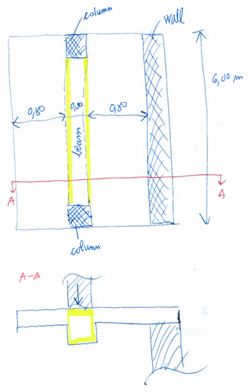
RC beam is partly integrated into RC slab. There is a bearing masonry wall on top of RC beam (over entire lenght of the beam). Since beam is almost 6 m in span, but distance from slab to wall is only 0,80 m, does that mean that load gets transfered through slab too since distance from beam to wall is short and loads always took the shortest path?

Im asking this because I get so much different results when calculating this as 2d problem in FEM software comparing to hand calculation where I only consider beam and a load on it.

nosilec_wuoceu.png
 
Replies continue below

Recommended for you

There are multiple load paths, which is good. So the structure will resist the loads as it wants, regardless of what you assume.

Not sure of the construction of the bearing wall above, but the first and probably predominant load path would be the wall/beam transferring the load directly to the columns as a deep beam.
 
Wall above RC beam is 1,40 m high masonry wall that supports rafters. So are you saying that masonry wall above beam + RC beam can act as deep beam (compression in masonry and tension in RC beam)?


22223_ifrcgd.png
 
Possibly, if the masonry wall is strong and stable enough. It will try to span in that fashion. Follow the stiffness.
 
Alright, one more question for you sir - how would you design RC beam in this case? What model/load would you use?

tnx for helping
 
I've given you some ideas. I'm not going to do your work for you.
 
Of corse not! but my opinon is that using deep beam model is too risky, but using just a RC beam and put a load on it is too conservative in my opinion.
 
Ok, I was just hoping to see which model you are more fond of since you seem to have experience with this.
Never mind.
You helped.
TNX.
 
OK. If you don't like using the reinforced masonry as a deep beam, just design the concrete beam to carry the whole load. The slab doesn't help, as it has no support on one end.
 
I think that most designers would put the full load to the beam and consider the wall's ability to span a nice bonus. Depending on construction, the beam may need to support the wall while it is constructed and cured anyhow.

I like to debate structural engineering theory -- a lot. If I challenge you on something, know that I'm doing so because I respect your opinion enough to either change it or adopt it.
 
I would definitely design the beam to support the load from the wall as well as the adjacent slabs in 1-way action. Take the additional load paths as an added bonus.
 
Your point about the wall taking load under FEM has merit too, of course. It'll happen. I'd include a light mesh of bottom reinforcing in the slab for crack control in acknowledgement of that.

I like to debate structural engineering theory -- a lot. If I challenge you on something, know that I'm doing so because I respect your opinion enough to either change it or adopt it.
 
Of course the slab need reinforcement also at the top because it is cantilever with bending tension on the top side
'many ways go to Rome'
as we say in Germany :)


best regards
Klaus
 
If you are in a cold climate, you may have an excellent opportunity for ice damming...

Dik
 
Load doesn't take the shortest path, it distributes to more flexible paths. That beam is 7.5 times as long as the distance to the wall. If the connection at the wall is fixed (stiff/thick wall, top reinforcing), it's like your beam is spanning 6m but the slab is spanning 1.6m simple span (0.8x2). Your slab is like a 6m wide, 1.6m long simple span beam. it can most likely theoretically support itself depending on load and thickness. My guess is that a very large portion of the load will go straight to the wall. I have access to RISA floor, and a very quick model would give me all the bending moments and deflections as a 2 way slab. You could consider it this way, or design the beam for the full load knowing that you feel comfortable with a D/C of 0.999. Most times I would probably just design for the beam cuz I can do that in a minute with a mental calc. If it's a one-off situation, adding a few pounds of rebar won't cost too much.
 
Aaron, might want to rethink that...

AaronMcD said:
Load doesn't take the shortest path, it distributes to more flexible paths.
Actually load distributes to paths with greater stiffness.

AaronMcD said:
If the connection at the wall is fixed (stiff/thick wall, top reinforcing)
Very likely not the case. There is no reason for trying to develop the top bars. It's hard (and pointless) to make that connection anything more than a hinge.

AaronMcD said:
1.6m long simple span beam
No, the slab cantilevers past the beam as can be seen in the plan and section.


n3jc,
Stick with designing the full load to the beam.
 
Aaron,
As depicted, the slab is not a simple span, it is a propped cantilever.
 
I don't know how to quote on this forum yet...

DETstru, yes, sorry meant more rigid path. Wording came out quite wrong!

Yes, if it is considered a hinge of course the load won't go there. I don't have all the details, just considering what OP said about load going to the wall, which would happen. Top bars will likely be hooked and developed. Depends on bar size, wall thickness.

Hokie66 & DETstru, Yes I see the slab cantilevers, but a cantilever is half a simple span, the easiest way to estimate if a cantilever will work. It depends on how stiff the wall and wall connection are.

Re-looking at the details, both the wall and the slab seem to be discontinuous at the intersection, so it may be quite flexible. In that case i would probably just ignore the wall as support, though theoretically it may take a good portion of the load.

 
AaronMcD,

There is no point in trying to develop a truly fixed connection from slab to wall. It's difficult to do regardless of whether or not you hook the top bars.

The only load that will go to the wall is from when the beam deflects. It's flange (the slab) will push down on the wall and that deformation creates the load. That might be completely countered by the rotation induced by the cantilever on the opposite side of the beam. This can be determined in an FEM analysis but there is no point to doing one.
It would not be wise to rely on that slab for supporting the wall whatsoever. Just provide some extra bar/mesh in the slab in case of cracking if one really wants to.

AaronMcD said:
Yes I see the slab cantilevers, but a cantilever is half a simple span, the easiest way to estimate if a cantilever will work.
Not sure I understand what you're getting at here.
 
Status
Not open for further replies.

Part and Inventory Search

Sponsor