Tek-Tips is the largest IT community on the Internet today!

Members share and learn making Tek-Tips Forums the best source of peer-reviewed technical information on the Internet!

  • Congratulations cowski on being selected by the Eng-Tips community for having the most helpful posts in the forums last week. Way to Go!

How can I change Normal arrow direction at draft analysis in catia V5

  • Thread starter Thread starter wowpilot
  • Start date Start date
W

wowpilot

Guest
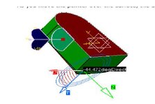
I want to use analysis under running point comment to see the draft angle on the surface but I dont understand very well. can someone help me about this issue ?
View attachment 1861.htm[/url]
 

Attachments

  • Asdasd.jpg
    Asdasd.jpg
    14.5 KB · Views: 6
Last edited:
Here's a quick tutorial in GrabCad that will get you started: https://grabcad.com/tutorials/can-anyone-explain-draft-analysis-in-catia-v5

In Step 6 you see colors applied to the part. Normally (depending on how the colors are set); green faces have enough draft to be removed from the mold, blue faces are at the draft angle limits, and red faces cannot be removed from the mold.

It was not what I asked actually. but thank you for info. I was asking how to change the direction of Normal arrow (shown in green color in the picture I attached)
 
The Running Point arrows are based on the shape of the surface at that location. None of the arrows can be reversed, or modified; it's just measuring the directions at the current location of the surface.
 
Last edited:

Part and Inventory Search

Sponsor

Back
Top