Paul H
Mechanical
- Feb 19, 2019
- 5
Hi, As you will see I'm no expert on GD&T but I have been involved in a discussion to try to reduce the number of concessions or scraped parts we produce as this has existed for many years as different manufacturing sites can interpret the drawing in different ways so the design intent isn't always clear. Some design offices ignore the 'rule' and allow a larger roundness tolerance than the size tolerance but other limit this to the max size control (which makes it harder to achieve!) and so we don't have a Standard practice across our design groups which is our ultimate aim.
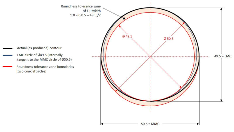
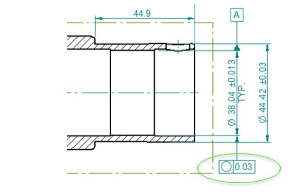
A bit of history first so you know our issues. We produce mechanical seals and the sleeve component must comply to a very tight tolerance (API) over the pump shaft (typically F7 h6) so the bore size of our sleeve is often controlled to +/- 0.013mm. Controlling this size is not the issue but maintaining a reasonable roundness control is the problem. If I understand this correctly and if we follow the rules of GD&T (ANSI or ISO)the roundness tolerance cannot be > than the size tolerance so as in this example the roundness cannot exceed 0.013mm.
The actual components are typically quite thin (<4mm section) and are normally just turned (not ground) so manufacturing struggle to hold such tight tolerances. typically they can maintain a minimum of around 0.03mm tolerance on roundness so my question is: is it possible to apply an 'average' size control (as we know there is enough clearance between the shaft and the sleeve bore) and allow the roundness tolerance to be larger then the size tolerance (as per the attached)?
Appreciate any help or advice you guys can offer
 (as usually, you are)