Continue to Site

Eng-Tips is the largest engineering community on the Internet

Intelligent Work Forums for Engineering Professionals

  • Congratulations IRstuff on being selected by the Eng-Tips community for having the most helpful posts in the forums last week. Way to Go!

Hip Beam to Tension Ring Connection on Stick Frame Pyramid Roof

Brick Jagger

Structural
Nov 28, 2023
6
Hi y'all,

I have a 24'x24' stick frame pyramid roof with vaulted ceilings on an exterior ramada. There are no collar ties, so I plan to take the thrust out with a tension ring. I have scoured the existing threads on here about the design of this type of roof using diagonal hip beams and a tension ring at the plate. Those threads are very informative and I learned a lot, but now I'm trying to detail the hip beam to tension ring at the corners and I would like some help or direction.

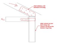
The detail needs to restrain the hip beam and transfer its thrust into the tension ring All I can come up with is using screws to connect the hip to plate and a strap around the corner to tie the tension ring together. See the attached sketch. Has anyone detailed this before and can provide suggestions? Thanks!
 

Attachments

  • Scanned Documents.pdf
    3.8 MB · Views: 25
Replies continue below

Recommended for you

I'd be surprised it you could get a screwed connection to work on a roof of that scale.
I usually end up doing a kinked flitch beam to support the peak in lieu of the tension ring strategy
 
Yeah I was having trouble finding strong enough screws for the thrust, which is somewhere in the 6-7 k range. Not to mention I'm not sure how to think about the load applied to the screws in that application. They seem like they would be simultaneously loaded in shear and tension.

I saw your previous posts about the flitch beam. So in that case, all thrust is taken out of the equation by the kink beam itself?
 
Yes... tension rings are all fun and games right up until it's time to sort the details.

You might be able to swing something with steel posts if that would pallatable.

c01.JPG
 
Unfortunately structural steel is not an option, but what is interesting about this project is the architect wants 2'x2' masonry columns. So I was also considering something like attaching the hip beam to the top of column in such a way to resist the thrust and strapping the tension ring beams to the column. Not sure if straps from wood to masonry columns are an option though...
 
With 24x24 columns, you may not need a tension ring. Probably easy enough to embed a large flag plate in the masonry to make a decent rafter connection.
 
No chance a screwed connection like you show will work. Definitely needs to be something more like what kootk drew above.

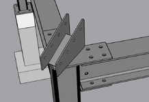
This is what I came up with for a recent project. Obviously this is a little different than yours because I had a steel frame below the wood framed roof, but I would expect a similar type of connection to the hip. This connection used (4) 1/2" bolts. This roof was also only 13'x17', so I expect your connection may be more substantial.

1749218112799.png 1749218145816.png
 
I saw your previous posts about the flitch beam. So in that case, all thrust is taken out of the equation by the kink beam itself?
Yes but for something of this scale you are probably looking more of a kinked I-beam.
 
I'm making the decision to go with a kinked flitch plate beam. Detailing a tension ring is NOT easy, like KootK said, and if I forego the tension ring, I don't like the permanent thrust on the masonry columns. They are large, but are still highly stressed and analyzing them in biaxial bending is tough.

The flitch plate beam calcs out pretty well if I am doing the design correctly. It seems pretty simple. I'm just analyzing the moment and shear at the kink and comparing that to the capacity of a fully braced steel plate. XR250, can you confirm if there are other considerations I'm missing?
 
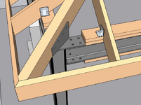
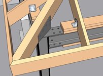
When you've got this staring you in the face, it's tempting to get rid of the bird's mouth somehow and just use the facia as the tensionrign.

c01.JPG
 
I'm making the decision to go with a kinked flitch plate beam. Detailing a tension ring is NOT easy, like KootK said, and if I forego the tension ring, I don't like the permanent thrust on the masonry columns. They are large, but are still highly stressed and analyzing them in biaxial bending is tough.

The flitch plate beam calcs out pretty well if I am doing the design correctly. It seems pretty simple. I'm just analyzing the moment and shear at the kink and comparing that to the capacity of a fully braced steel plate. XR250, can you confirm if there are other considerations I'm missing?
Deflection usually controls these things for me - especially at 24 ft. I am surprised a plate is calc-ing out in lieu of an I-beam.
 
When you've got this staring you in the face, it's tempting to get rid of the bird's mouth somehow and just use the facia as the tensionrign.
With the steel here, that wasn't the approach I took to resist the outward thrust on my project, but it's a good idea. If the geometry works out similarly and you could rely on direct bearing between the hip and fascia boards, then you would just need a 90 degree bent/welded steel plate to connect fascia to fascia. Maybe the fascia boards could even be one piece, 24 ft long LVLs which would eliminate the need for any intermediate splicing. The economy of this would be hard to beat.
 

Part and Inventory Search

Sponsor