Continue to Site

Eng-Tips is the largest engineering community on the Internet

Intelligent Work Forums for Engineering Professionals

  • Congratulations waross on being selected by the Eng-Tips community for having the most helpful posts in the forums last week. Way to Go!

Help with Design on Motorized Tool Dolly

Status
Not open for further replies.

goodblasson

Mechanical
Aug 27, 2008
4
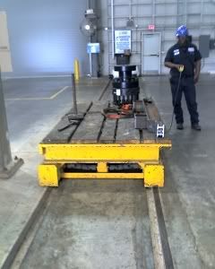
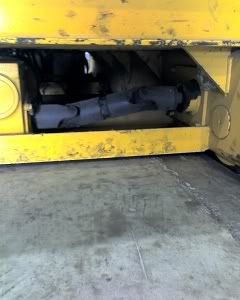
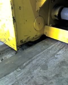
Hello Guys, this is my first post so go easy on me. I am working on a project at work, I have to design a motorized cart that can move up to a 5,000lb load. The cart is 72" long, 27" wide, and 30" tall, it has arms that hold rollers which a 8" diameter tool sits on the rollers. The cart has to move up to 3mph and the 4 wheels are 8" diameter and made of steel and roll on inverted angle iron(like a train track). Anyhow, the customer wants to see a DC motor used and have the power supply onboard. It has to have some kind of control to start slow and gain speed up to 3mph and slow down to stop. My problem is that I can not find a DC motor and gear setup to propel the cart at 3mph and handle the load. Can anyone give me any input or suggestions please? I was thinking of buying a motorized pallet jack and modify it so that I can connect it to my cart for propulsion. But obviously thats the cheap and ugly way out of my problem. I am including a picture of a cart another customer uses, but they will not give me any details to the build so I am on my own....

KnightRail2.jpg

KnightRail3-1.jpg

KnightRail4.jpg

 
Replies continue below

Recommended for you

goodblasson,

Why can you not find a DC[ ]motor and gear setup? There is lots of stuff out there.

Can you attach a cable to this thing?

How much acceleration and deceleration do you need?

Do you need to be able to make sudden emergency stops?

Are there any other safety issues?

Do you need to be cheap, or powerful and efficient?

Do you need to be able to position the table accurately? This affects torque.

JHG
 
goodblassen,

I would think that finding a DC motor would be easy. DC motors can have huge stall torques. Steel wheels on steel rails should roll easy enough that the rolling friction should be minor compared to the inertia of the cart and load. The critical question is: How fast do you have to accelerate it? A slow start means a smaller motor. I'll bet you can do the job with less than 1 hp unless they want really fast acceleration. Look at , they have a big selection of DC motors and controllers. Will it be powered by batteries?

Timelord
 
1.) You don't necessarily have to use a u-joint drive shaft if you can align the reducer output with the wheel axle.

2.) If you use v-groove wheels on both sides the tracks will need to be aligned fairly closely. Another way to accomplish this is to use v-groove wheels on one side only with flat or crowned wheels on the other. This is much more forgiving.

3.) You need to realize that the wheels are not captured and will not resist a large overturning moment.
 
And more importantly, how do you plan to stop it?

Friction? Regeneration? A combination?

 
Thanks for all the replys. As far as acceleration goes, I know the customer wants max speed of 3mph, but the cart only has to move 15 ft both ways, 30ft long rail. There is no specification to how much acceleration is needed, I assume a slow steady startup and acceleration would be best(slower is better.) How am I going to stop this thing? I was hoping to use some kind of rheostat, therefore I could bring it up to speed and decelerate to a stop according to how I operate the rheostat. The customer would like to see this thing battery powered thats why I am looking for a DC motor. If all else fails, I can use an AC motor with a power cord that hangs from the ceiling with one of the retracting devices so that the cord is never really in the way. Assuming I can agree on a motor for this application my next question will be how am I going to transmit power from the motor to the live axle? I was hoping to get away with a chain drive and sprockets b/c the cost of the u-joints are very high and that makes this project that more complicating for me. Ultimately there is no budget that I have to stay within, but for the sake of being a good manufacturer, I would like to make it as affordable for the customer as possible.
 
goodblasson,

If you are travelling 15ft at 3mph (4.4ft/sec), you are seeing significant acceleration. You have 7.5ft to hit 4.4ft/sec, and 7.5 to decelerate back to zero. You would be better off knowing how long your system should take to move from one position to another. 3mph may be a bit fast. Abrupt acceleration may cause something to move or tip over.

There is still lots of hardware out there. You want a reducer with a high reduction ratio and high efficiency, such as harmonic drive. There are quite a few alternatives. Forget about worm drives as they are inefficient. A large gear reduction means a smaller motor.

The engineering here does not sound complicated to me. A clear understanding of the requirements sounds much more challenging.

JHG
 
I would look at using a hollow-shaft reducer (with a torque arm), and let the drive shaft support the reducer with in-board flange bearings adjacent to the wheels supporting everything. No sprockets and chain.

I don't think this cart will have much of a duty-cycle to warrant the extra expense of more expensive reducers, so I would go with the worm-gear. As far as braking, I would look at a light-brake-torque brakemotor. You don't want a heavy brake torque to cause abrupt stopping.
 
That's fairly quick and short movements for a 5,000lb load. I think the components in your drive system need to be looked at closer. Has there been any discussion of using a hydraulic drive system?

"Art without engineering is dreaming; Engineering without art is calculating."

Have you read faq731-376 to make the best use of these Forums?
 
Might want to Google on Tow motors. There are a number of companies (Clark comes to mind) that build electric pallet jacks - which is what this seems to be or at least similiar.
 
Your acceleration is not just limited by the motor ‘strength’ is limited by the wheel slippage. 5000+ lbs is a lot of weight but the Coefficient of Friction of steel on steel changes in different environments. If this is outside in the rain it will be different if it is inside dry or if it is covered in oil and grease…all that factors in.

Is 3mph your limit or your goal. I would say that over such a short distance it would be best to be slow.

Subway systems are powered through the rails. Would an electrified rail be too big of a safety concern? I don’t know if subways are AC or DC. I would think DC but I may be wrong.
 
The cart will be used indoors and in a clean environment. 3mph is more of a goal than a requirement. It cannot exceed 3mph and 1.8 to 2mph is really my goal. How many rpms does the motor need to turn or what is the output rpm of a speed reducer if I am using 8" wheels and want to factor in slippage to move at 2mph.
 
goodblasson,

The RPM of an 8" wheel at 2mph is easily figured out by anyone with engineering training. Particularly since your device is battery powered, some engineering type will have to throughly analzye your drive train for torque, speed and power consumption.

Someone in-house at your end ought to know how to do this.

JHG
 
Goodblasson,

The weight of your car plus its 5,000 pound payload traveling at 3 mph is more than sufficient to kill someone.

Your demonstrated inability to derive a required acceleration given top speed and distance, and to calculate wheel rpm given speed and diameter suggests that you don't have the necessary knowledge to safely design something like this.

I suggest that you hire an engineer.
 
Wow MintJulep kind of harsh, BUT correct.

Anyone that designs anything should always keep in mind: Someone will use this and if I make a mistake someone could die. You do not want someone to die because you thought you could do something you don't know very much about.

I always have ALL of my work check by at least on other engineer even when it is not required. I do this because I never want anyone hurt or killed because I made an error.

Small error on paper equals blood in the real world.
 
Well guys if you pay attention to detail, I did ask for input figuring out my RPM's relative to SLIPPAGE. Im trying to determine if I will have slippage and if so how can I factor that into my analysis. Safety is absolutely priority in my field of work. I am plenty able to determine speed and acceleration, however I was coming to this forum to try to get opinions and ideas outside of my own thinking. I wanted a different set of eyes to look at what I am designing here. No offense is taken, as I knew I would catch hell for asking the question in the way I did.
 
Forget about slippage. You can't calculate it. You should engineer around it. One way that I have worked around the slippage issue is to have polyurethane tired drive wheels that were adjustable. In my case we used pneumatic cylinders to pust the tires onto the track, but you could accomplish the same with screws and springs. You would still need to have your steel load bearing wheels, but the drive wheel(s) would be poly.
 
goodblasson,

I live in a city with streetcars, which run on tracks on the road. I do not see much slippage of the metal wheels on the metal tracks. In your application, with its low speeds and accelerations, I would ignore this.

If this really matters to you, you could use a rack and pinion to move your dolly.

JHG
 
Goodblasson
Just my two bob's (20 cents) worth.
I have built many "shuttle" cars over the years carrying similar loads-first forget speed (MPH)as the main design criteria-how long do you have to move from point A to point B.
Lets say 30 seconds to move 15 Feet= 30 feet per minute=1800 feet per hour=0.34 MPH(average).
At these speeds, acceleration/deceleration issues are miniscule.
My normal method of drive is to use flange wheels (overhead crane type) with one wheel having a "ring" gear cut into the outer boss of the wheel, a pinion on the motor direct meshing with the ring gear- the other three wheels are just idlers. The gearmotor can be a flange mounted type.
Power supply to the trolley can be by overhead catenary cable, travelling busbar or by retracting cable reels.
You can use two speed brake motors-slow speed to start and stop, high speed for the majority of the travel time-changeover of speed by proximity switch sensing on start up and slowing down-or with vsd type drives with adjustable ramp up/ramp down characteristics.
All the controls can be onboard mounted which reduces the amount of cables running to the car.
Safety issues-fit a crash bar/limit switch to either end of the car, interlocked into an emergecy stop circuit to stop the car dead if it contacts an obstruction-fit fences around the total track as well.
My "rough" estimate for a drive size is 0.55 Kw at 30 fpm(friction factors are very low), but discuss the drive motor requirements with a supplier who services the overhead crane industry- this type of application is no different to a long travel crane.
Trust that this helps.
Ross
 
Ross,
I think you have just described a standard overhead travelling crane conguration. Do you expect any crabbing with just one driven wheel?
Regards,
Bill
 
Status
Not open for further replies.

Part and Inventory Search

Sponsor