Hello,
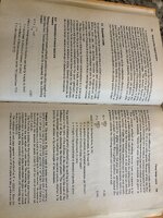
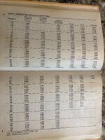
I’m a 3rd-year mechanical engineering student currently doing an internship in the piping discipline. Most of my work involves reviewing and building calculation sheets based on graph references, and I’ve been using the Design of Piping Systems by the M. W. Kellogg Company, particularly the graphs in Appendix C-7 and C-9.
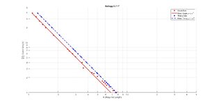
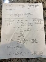
So far, I’ve been able to derive the equation behind the C-7 graph, which represents anchor leg flexibility for in-plane displacement, using:
Where:
(where Δ is the normal displacement), but it doesn’t seem to match the shape of the graph.
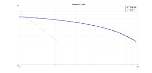
I extracted approximate data points from both graphs manually and plotted them in MATLAB alongside the theoretical equations.
Does anyone know the formula or method to derive the equation behind the C-9 graph? Or could anyone offer a hint on how the normal displacement is accounted for in the anchor leg stress equation?
Any insight from those who’ve worked with this reference before would be greatly appreciated!
Thanks in advance.
I’m a 3rd-year mechanical engineering student currently doing an internship in the piping discipline. Most of my work involves reviewing and building calculation sheets based on graph references, and I’ve been using the Design of Piping Systems by the M. W. Kellogg Company, particularly the graphs in Appendix C-7 and C-9.
So far, I’ve been able to derive the equation behind the C-7 graph, which represents anchor leg flexibility for in-plane displacement, using:
S = (3 * E * D * Δ) / L²
Where:
- S = Allowable anchor load
- E = Young’s modulus
- D = Pipe diameter
- Δ = Thermal expansion
- L = Required Leg length
Δ' = √[(L)² + Δ²] − L
(where Δ is the normal displacement), but it doesn’t seem to match the shape of the graph.
I extracted approximate data points from both graphs manually and plotted them in MATLAB alongside the theoretical equations.
My question is:
Does anyone know the formula or method to derive the equation behind the C-9 graph? Or could anyone offer a hint on how the normal displacement is accounted for in the anchor leg stress equation?
Any insight from those who’ve worked with this reference before would be greatly appreciated!
Thanks in advance.