Continue to Site

Eng-Tips is the largest engineering community on the Internet

Intelligent Work Forums for Engineering Professionals

  • Congratulations waross on being selected by the Eng-Tips community for having the most helpful posts in the forums last week. Way to Go!

Grillage Analogy 1

Status
Not open for further replies.

Shz713

Structural
Aug 21, 2015
221
Good day y'll;

I have some questions with respect simplifications made in bridge grillage model. I have read 'Bridge deck behaviour by Hambly' and 'bridge deck analysis by O'Brien'; but couldn't find what I was looking.

-If the cross section of deck varies throughout each span (e.g. thickness of web or slab is varying), should neutral axes changes accordingly? Or average is taken? NA is needed for calculating second moment area, cross sectional area

-I know that 'dummy members' are used to transfer the loads such as parapet load. How their properties are calculated?

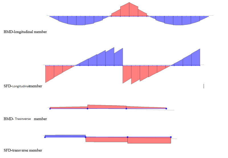
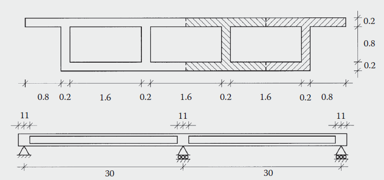
Enclosed is a grillage example by Hambly for refreshing the concept!

Shoot for the Moon, even if U miss, U still land among Stars!
 
 http://files.engineering.com/getfile.aspx?folder=5461fc8c-08ba-4cc9-ad6f-1e7d10a6c848&file=grillage_example_Hambly.pdf
Replies continue below

Recommended for you

Hi Schz713,

First of all, check out this link Hambly is definitely a very good definitive reference, but I found this link to be a good introduction thats a bit nicer to look at.

(1) For longitudinal grillage members, I would advise taking into account the different height of the neutral axis for varying beam depths. A good example is a steel-composite bridge with a haunched girder that varies in depth. In my FE software (LUSAS) you can do this by specifying an eccentricity when inputting section properties. If the change is very modest i.e. transition from span-pier region with a constant construction depth I wouldn't bother. Likewise if you have a slab that haunches transversely I'd simply take an average (it really comes down to how refined your grillage is at the end of the day. It's an approximate method, and should be treated as such.

Generally the NA of transverse and longitudinal members are assumed to be coincident; (this is ultimately one of the limitations of the grillage analogy). If you look around, there's a chunk of material which goes into this matter in some detail.

(2) The use of "dummy members" is definitely a means of account for load that otherwise lies outside the extent of your grillage like the s/w of concrete edge beams and parapets for example. However, modern FE packages should enable you to specify "patch loads"; these are like UDL's but are really a very heavily concentrated "patch" of point loads that the software will then distribute to the relevant parts of the mesh.

To answer your specific question, the principle behind use of so-called "dummy members" is to "catch" the loads outside the grillage and distribute them to the structural model. The section properties should be arbitrarily small such that their presence results in a negligible increase in stiffness to the actual thing you're modelling. By "arbitrarily small" I might for example use the section properties of a 50x50x5 SHS, if the grillage is idealising a 200m long viaduct with 60-70m long spans. I strongly recommend calculating actual section properties for a given section rather than using A=0.00001m2 and the like; if you have section properties with many orders of mangitude difference this can lead to so called "ill-conditioning" and lead to round-off errors and the like.

I've given you a very simplified explanation and no doubt some of the above will not be 100% technically correct, but hope some of this helps! I'd recommend reading the manual of the software you're going to use to actually model whatever it is you're analysing; hopefully it'll have some worked examples in that are suited to your needs. Good luck!
 
Dear UKBridge,

Thanks heaps for explanations. The link was very informative about basic premise involved in FE modelling and grillage. For cross section variations, if you looked at the bottom slab of enclosed example, the bottom slab thickness (more precisely 'soffit slab' as for cellular deck) is varying thickness along the span. I have considered this variation for making the flexural and torsional properties. This affects the center of gravity of slabs and in turn the physical properties. Though, to me is more convenient to take the average so I'd have constant center of gravity which ease the calculation of member properties.

I am using SAP2K for making the grillage. Based on Hambly and Surana (grillage analogy in bridge deck analysis)for interpretation of cellular deck grillage output, they said the longitudinal moments for true bending design should be average of moments at each side of joints. How about shear force in longitudinal members? Can it be read directly from the grillage output?

For slab bending, it is mentioned assuming that points of contraflexure lie midway between the webs, the moment at each end of a slab is simply the shear force it carries multiplied by half the distance between webs. This assumption is due to the shear area of transverse members which postulated to be midway between webs (while for longitudinal members is takens as weba area). But this is too conservative, in my case the actual transverse moments contraflexure points (point of zero-moments) is not located between webs. In this case, I just take the shear force of transverse members and multiply by half distance between webs? Imagine that girder spacing is changing due to web thickness variation, this make the estimated slab flexural moment double-conservative. There's whole different story for getting slab design moments, which should be referred to Pucher charts for local moments (rotations about planar axes, Mx & My).

Shear torsion flow is well-explained. I reckon the only output for cellular deck which can be directly taken from grillage result is reactions and vertical deflection.
Below I have enclosed bending moment and shear force of longitudinal and transverse members. Any suggestion is appreciated
123_sdbq0h.png


Shoot for the Moon, even if U miss, U still land among Stars!
 
Glad it was helpful! I find that website coming in useful a lot; the SCI (Steel Construction Institute) also have a lot of publications which deal with this sort of thing.

It's really hard to give you any help without seeing the actual thing you're modelling. As i discussed somewhere it really comes down to how much whatever it is youre idealising as grillage varies in depth. I'll answer what I can:

I am using SAP2K for making the grillage. Based on Hambly and Surana (grillage analogy in bridge deck analysis)for interpretation of cellular deck grillage output, they said the longitudinal moments for true bending design should be average of moments at each side of joints. How about shear force in longitudinal members? Can it be read directly from the grillage output

Yes, if you're using actual "grillage" elements you'll need to take an average of bending moments due to the saw tooth-like shape of the diagrams. (I would just take the worst case tbh unless you have an extremely crude mesh). Don't forget that these bending moments and shear forces are per "grillage width". I.e. if your cellular beams/whatever are spaced at 2.5m centres, you will obviously get bending moments and shear forces in kNm/2.5m run and kN/2.5m run.

For slab bending, it is mentioned assuming that points of contraflexure lie midway between the webs, the moment at each end of a slab is simply the shear force it carries multiplied by half the distance between webs. This assumption is due to the shear area of transverse members which postulated to be midway between webs (while for longitudinal members is takens as weba area). But this is too conservative, in my case the actual transverse moments contraflexure points (point of zero-moments) is not located between webs. In this case, I just take the shear force of transverse members and multiply by half distance between webs? Imagine that girder spacing is changing due to web thickness variation, this make the estimated slab flexural moment double-conservative. There's whole different story for getting slab design moments, which should be referred to Pucher charts for local moments (rotations about planar axes, Mx & My).

Don't understand this bit sorry! By "webs" do you mean the webs of the cellular deck, or something else? Need a sketch really. Calculate shear areas using the formulae in Hambly, some packages (not sure about SAP2000) allow you to create the geometry using surface elements and ouput detailed section properties for you. I would forget about puscher charts and the like until you figure out your global analysis, they are very different things.


Shear torsion flow is well-explained. I reckon the only output for cellular deck which can be directly taken from grillage result is reactions and vertical deflection.
Below I have enclosed bending moment and shear force of longitudinal and transverse members. Any suggestion is appreciated


No, bending moments and shear forces can all be used for design purposes provided the grillage is properly constructed. I'd need to see a plan of your model before commenting on yours though!

 
Thanks for detailed answers.

For longitudinal moments, to get the finalized value of bending and shear forces, I have to multiply by the longitudinal meer spacing, which in my case is 2.59m.
For slab bending moment, I have attached the explanation given by Hambly. Yes I means the webs of cellular deck (my model is similar to the example I attached in my earlier post). Actually I did calculated member properties (e.g. shear areas and etc.). For other bridge type like slab-on-beam or voided slab, the output interpretation is different to that of cellular decks. I'm perplexed to read the slab bending from the grillage, since it has to be obtained from the shear force but I'm lost in that point!

regards


Shoot for the Moon, even if U miss, U still land among Stars!
 
 http://files.engineering.com/getfile.aspx?folder=81daf639-f262-44ca-ac85-76dd905a6d47&file=grillage_output_interpretation.pdf
Hey shz713,

Hows it going?

Apologies, to be honest i didnt think youre analysing a deck like the one actually showed in the extract of hambly ie a post tensioned box girder type structure. For this type of structure a grillage is actually a bit more complicated, I dont have a copy of hambly on me but i think the heavily bold lines are so called stiff outriggers (i could be wrong).

No, you dont have to multiply the grillage output by 2.59m for a general grillage i.e. A slab. By that i mean the bending moment outputted is that for 2.59m worth of slab. So for a simple slab case you would calculate how much reinforcement you need for a 2.59m wide slab. For your specific example its more complicated and really outside my knowledge without doing a bit of reading.

Unfortunately i dont think its appropriate to give any more help without sketches and the like, with screenshots of your model as its extremely easy for me to give you incorrect advice based on incorrect assumptions about your work. Im not sure what you mean about reading the slab bending from the grillage using the shear force; i think you definitely need a bit of help from someone in your organisation whos worked on this type of problem before as a lot of this stuff is down to interpretation.

Ive been down this route before as an inexperienced engineer; often theres too many directors and grad engineers but not enough people inbetween! I dont want to/ cant help you with the grillage but ill leave some advice:

1. Calculate bending moments on a simple line beam model. Then apportion this total bending moment to each web and associated width of top and bottom slab based on their own EI. Your grillage if correct should roughly approximate this distribution. NOTE you should not use this approach to actually determine global moments and shears!

2. Look at the shear force diagrams, are there are any high shear forces in regions of your model which dont make any sense? I.e. Is the load path your grillage telling you making any sense?

3. Are there any discontinuities in your model ie areas where your mesh is broken? Have you checked the sum of the reactions so that all the load is correctly applied?

Good luck, Pete

 
Yes, I admit that.
For cellular deck the interpretation of forces is a bit harder to interpret in comparison to slab-on-beam/steel plate/voided slab decks. I will do a simple single cell cellular deck and carry out hand calculation to work the load effects.
In my model shear values are not very high (snapshot was exaggerated view), I cross checked the FE model.

Just one enquiry about applying truck loading, what if the wheel load is located outside main members; how to distribute it to neighbouring members? Thanks

Shoot for the Moon, even if U miss, U still land among Stars!
 
Hi again,

If diaphragm is present in a deck (either at intermediate or end supports), for grillage transverse members the effective length of flange (top and bottom slabs if any) must be taken into account. Mass of deck slabs are already considered in longitudinal section property calculation and for transverse member properties the deck slabs are usually given zero mass. In that case, what mass property (full/half/zero) must be assigned to those transverse members that include diaphragms? I did not include deck slabs as flange of diaphragms and calculated them separately to avoid overcompensation of deck slabs mass in longitudinal and transverse directions.
Front and longitudinal section of deck is shown below.
Any response is appreciated

Capture_jfrjtq.png


Shoot for the Moon, even if U miss, U still land among Stars!
 
Status
Not open for further replies.

Part and Inventory Search

Sponsor