Hey there,
my name is Basti and i'm working on a power test bench for my masters degree in electrical engineering.
That power test bench is supposed to measure the power of certain, smaller vehicles like go-karts right on the wheel hub. Therefore i have two servo drives controlled by a plc.
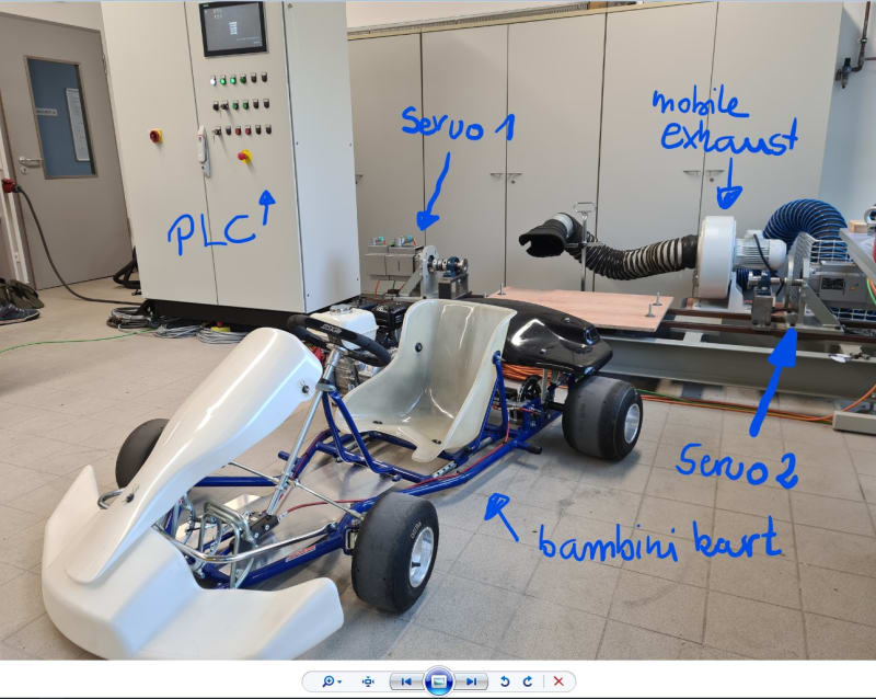
fig. 1: repressentation of test bench device / construction.
Those karts have a rigid rear axle without a differential or any suspension. E. g. one vehicle has a combustion engine. It's a HONDA GX200 engine with 4.8 kW maximum power output.
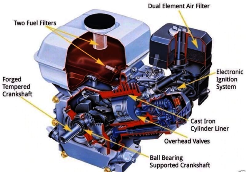
fig. 2: Representation of a HONDA GX200 one piston engine
The crankshaft leads into a oil-soaked automatic centrifugal clutch followed by two chain drives (gear ratio i = i1 * i2 = 2 * 2.5 = 5).
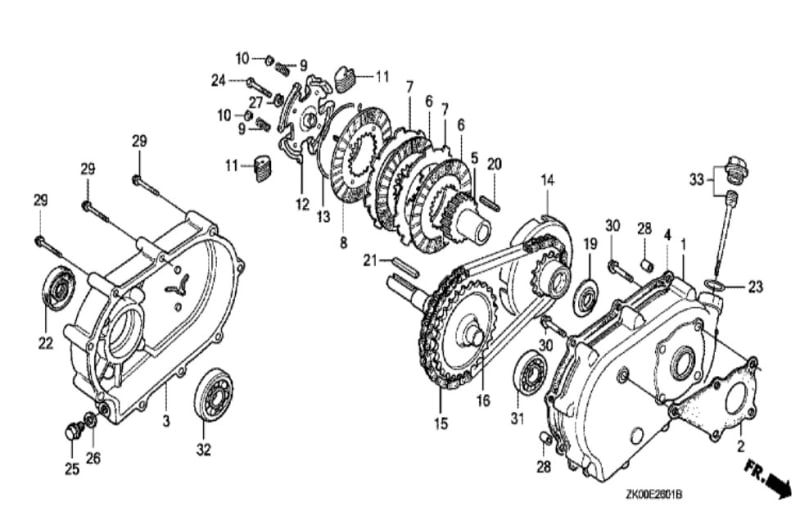
fig. 3: Representation of centrifugal multi-disc clutch
Further i attached certain measurement equipment right on the rear axle and can measure speed and torque at one side.
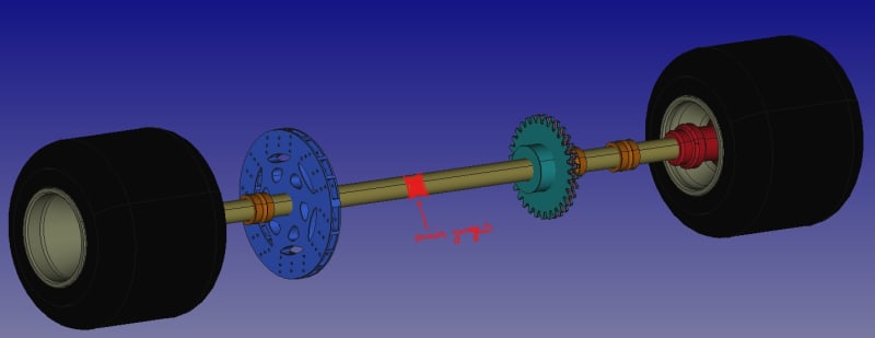
fig. 4: Rear axle CAD reverse engineering in freeCAD. That red mark dertermines the position of measurement equipment (strain gauges and Hall sensor).
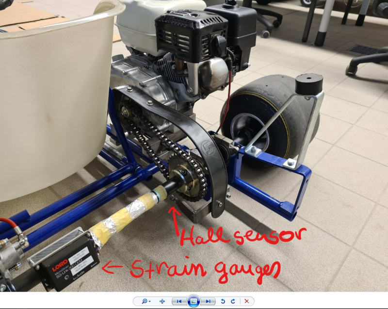
fig. 5: A part of the real rear axle.
To verify the test bench, i need to exactly figure out, what forces and torques take effect on whatever position in the drive chain.
Recently i also applied a hall sensor right on engine's flywheel, so i can additionally measure engine speed as well.
Simplified vehicle dynamics includes:
whereat
- T_Drive is the engine torque on the crankshaft. It's the reservoir, what is max available
- T_Acc is the acceleration torque to speed up translational and rotational masses. It only appears if velocity =/= (unequal) constant and is defined by T_Acc = m_T*α*r² + J*α (whereat m_T = translational mass, α = angular acceleration, r = radius, J = moment of inertia)
- T_Air shall be counter torque caused by air drag
- T_Roll shall be rolling resisting toque caused by every wheel-road contact
- T_i shall be inner resistance like friction in wheel bearings, friction in clutch case, friction in drive chains etc.
and
- T_Slo is the resistance caused by a gradient on the road (resistance force times wheel radius)
So, in general, the vehicle can only use the mentioned reservoir to accelerate the masses. If no friction wouldn't exist T_Drive would be identical to T_Acc. With friction it's less. Regularly you can directly measure the wheel power (engine's power after reductions, what remains at the wheel-road contact spot) e. g. by a roller type dynamometer. While doing so you are missing air drag, translational acceleration and gradient resistance. The resisting moments, which reduce engines torque to effective engines torque on the rear axle could be estimated by a coast down measurement. While that measurement you gonna speed up to maximum velocity, decouple the clutch and freewheel to way lower speed. In that case the equation turns to:
whereat
- the drive torque should be zero, because the drivetrain is decoupled
- the resistances aren't 0 and reduce the current speed little by little, because a negativ acceleration must act
Regularly you would say: 'oh fine. T_Acc = - T_Res'. You would know your speed drop down, which is directly measured, know your moment of inertia and could quantify the driving resistances.
Unfortunately in my case it's not simple as this...
First of all:
Since the recently added engine's speed measurement it's obviously, that the clutch doesn't really decouple while coast down runs.
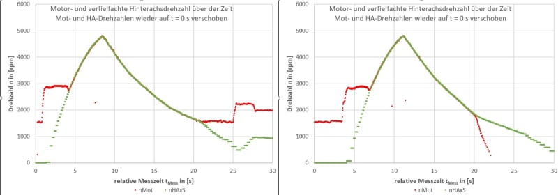
fig. 6: representation of acceleration and coast down runs on the road
In figure 6 i printed the speed measurement of two different acceleration and coast down runs. Those runs i did on the road with that gokart pictured above. You can see the speeds, measured in [rpm], over the relative measurement time t, measured in on either side. In each case the red line maps the engine speed and the green line maps the speed of the rear axle constantly multiplied by 5 ( x5 to better compare trends (remember all in all transition was 5)). The engine's idle speed is round about 1500 [rpm]. In each case the trottle is constantly kicked down to 100 % until maximum speed is archieved. Thenceforth it's fully droped to 0 % to coast down. The left hand side chart is the run, at which there is only the trottle drop off. The right hand side chart is a run, at which additionally the ignition is turned off. I hoped, while doing so as well, i could force the engine to instantly drop down to zero speed, to not get any ignitions in the combustion chamber. Buuuuut it's not. In both cases the secondary side of the clutch is dragging the primary side of the clutch - and thereby the crankshaft - to it's speed. In one case, there are ignitions and the engines resistance should be a little less. In the other case, there arn't any ignitions, so the drive chain is fully dragging the engine and the engine's resistance should be a little higher. You need to know, that those gokarts have homemade firing if the ignition is switched on (ignition coil and passing persistent magnet on flywheel). The left chart illustrates, that the engine does not decouple before idle speed.
So in fact i get the speed trends while coast down, but i cannot estimate the resisting torque or forces, because i'm missing the engine's inertia. This leads to ..
Second:
I'm missing the engines inertia to calculate the resisting torque from one of the coast down runs:
But why i need to know that? Because to verify the test bench i need to know what kind of force / torque i have to simulate on test bench and which not. E. g. while driving in the outside, the engine is speed up translational masses, rotational masses, overcomes airdrag, rolling resistance, inner forces, slope and rolling resistance. While mounted on the test bench the engine only speeds up the kart's rotational masses, overcomes the kart's inner resistances and a little additional resistance of pillow block bearing to mount the go-kart, and of servo drive bearings and rotational masses. There is no air drag, there is no rolling resistance on the indoor test bench. The test bench has to simulate that and to calculate this i need to know the engines inertia (equation above).
So far i coupled the drivetrain to one of the servo drive. I ramped up the speed in certain manner and got the torque to doing so. Out of this i got the effective moment of inertia of the drivetrain without the engine (which is seen by servo). This is because, while doing so - motor the sencondary side of the clutch - i don't get any rotation to the primary side of the clutch. So i only have got an estimation of secondary drivetrain inertia of 0.0626 kgm². But its missing the engine. And the engine's inertia is multiplied with i² to an effective inertia right on the rear axle (so in my case x25). I cannot leave it unknown.
Further the general handling of unknown inertias with a certain mass factor is also not possible. Those factors are undocumented and the translational and rotational masses are to close to each other to just say: 'oh i take a regular vehicle mass factor like 1.1'
Third:
So far i always think, that the measured torque on the rear axle should be the effective T_Drive - from equation above - which is reduced by transmission losses but powers the rear axle. That measurement equipment on rear axle gives exemplary trends like this:
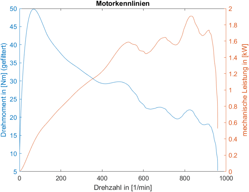
fig. 7: Representation of measured torque and calculated power whilst an acceleration run
The y-axis on the left hand side shows the measured one-sided-rear-axle-torque in [Nm]. The right hand side y-Axis shows the resulting mechanical power in [kW] (P = T*2*π*speed). The x-axis carries the rear axle speed in [rpm].
Virtually the engine's drag force, which takes action in the sprocket on the rear axle, is a reduced drag force, an effective drag force. It should not be the drag force from the crankshaft.
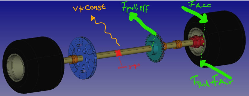
fig. 8: Schmematic of actually forces while accelerating.
It already overcame the losses in the clutch case and through the drive chains. If that effective drag force is greater than the instantaneous resistance force, which take action in the wheels, then there is a little reservoir to accelerate translational and rotational masses only of the rear axle? (since the effective drag force already and additionally overcame the rotational parts in clutch case and parts before rear axle?) If velocity and speed are unconstant, the effective drag force is high enough, there is an acceleration force, which also act against effective drag force. So if i look on the equilibrium state of torques, ...
.. isn't that meaning, i'm always measuring the effective T_Drag,eff? If i would calculate, even if i would exactly know the resistances, the inertia from that torque and speed ramp up, wouldn't it mean, that i only could calculate the inertia of the rear axle?
Is there anybody out there, who see my dilemmas and have a nice idea, how i can get to the engines inertia? If i finally could get this, i finally could say to my testbench: 'Servos! At this speed you do xyz resisting torque, at that speed you do xyz resisting torque' and so on. So that finally everything is determined like a road test in the outside.
I would really appreciate, if someone could help me to carve out the drawbacks. The dilemma is, in a motor-driven run i cannot decouple the clutch in a coast down. In a servo-driven test run i cannot couple the clutch to accelerate the non-ignition engine as well. How do i get the whole inertia?
Many thanks in advance![[worm]](/data/assets/smilies/worm.gif "[worm] [worm]")
Basti
p.s.: Please excuse my weird using of which, what, on, at etc. I'm sure there are a bunch of failures. Not to mention the grammar. I still hope you can get my intention
p.s.2: Your forum is great. I never wrote in a forum like this. It's finally so easy to illustrate pictures and attach something. Thy for it!![[glasses]](/data/assets/smilies/glasses.gif "[glasses] [glasses]")
my name is Basti and i'm working on a power test bench for my masters degree in electrical engineering.
That power test bench is supposed to measure the power of certain, smaller vehicles like go-karts right on the wheel hub. Therefore i have two servo drives controlled by a plc.
fig. 1: repressentation of test bench device / construction.
Those karts have a rigid rear axle without a differential or any suspension. E. g. one vehicle has a combustion engine. It's a HONDA GX200 engine with 4.8 kW maximum power output.
fig. 2: Representation of a HONDA GX200 one piston engine
The crankshaft leads into a oil-soaked automatic centrifugal clutch followed by two chain drives (gear ratio i = i1 * i2 = 2 * 2.5 = 5).
fig. 3: Representation of centrifugal multi-disc clutch
Further i attached certain measurement equipment right on the rear axle and can measure speed and torque at one side.
fig. 4: Rear axle CAD reverse engineering in freeCAD. That red mark dertermines the position of measurement equipment (strain gauges and Hall sensor).
fig. 5: A part of the real rear axle.
To verify the test bench, i need to exactly figure out, what forces and torques take effect on whatever position in the drive chain.
Recently i also applied a hall sensor right on engine's flywheel, so i can additionally measure engine speed as well.
Simplified vehicle dynamics includes:
Code:
T_Drive = T_Acc + T_Air + T_Roll + T_i + T_Slo- T_Drive is the engine torque on the crankshaft. It's the reservoir, what is max available
- T_Acc is the acceleration torque to speed up translational and rotational masses. It only appears if velocity =/= (unequal) constant and is defined by T_Acc = m_T*α*r² + J*α (whereat m_T = translational mass, α = angular acceleration, r = radius, J = moment of inertia)
- T_Air shall be counter torque caused by air drag
- T_Roll shall be rolling resisting toque caused by every wheel-road contact
- T_i shall be inner resistance like friction in wheel bearings, friction in clutch case, friction in drive chains etc.
and
- T_Slo is the resistance caused by a gradient on the road (resistance force times wheel radius)
So, in general, the vehicle can only use the mentioned reservoir to accelerate the masses. If no friction wouldn't exist T_Drive would be identical to T_Acc. With friction it's less. Regularly you can directly measure the wheel power (engine's power after reductions, what remains at the wheel-road contact spot) e. g. by a roller type dynamometer. While doing so you are missing air drag, translational acceleration and gradient resistance. The resisting moments, which reduce engines torque to effective engines torque on the rear axle could be estimated by a coast down measurement. While that measurement you gonna speed up to maximum velocity, decouple the clutch and freewheel to way lower speed. In that case the equation turns to:
Code:
T_Drive = 0 = T_Acc + T_Res- the drive torque should be zero, because the drivetrain is decoupled
- the resistances aren't 0 and reduce the current speed little by little, because a negativ acceleration must act
Regularly you would say: 'oh fine. T_Acc = - T_Res'. You would know your speed drop down, which is directly measured, know your moment of inertia and could quantify the driving resistances.
Unfortunately in my case it's not simple as this...
First of all:
Since the recently added engine's speed measurement it's obviously, that the clutch doesn't really decouple while coast down runs.
fig. 6: representation of acceleration and coast down runs on the road
In figure 6 i printed the speed measurement of two different acceleration and coast down runs. Those runs i did on the road with that gokart pictured above. You can see the speeds, measured in [rpm], over the relative measurement time t, measured in
So in fact i get the speed trends while coast down, but i cannot estimate the resisting torque or forces, because i'm missing the engine's inertia. This leads to ..
Second:
I'm missing the engines inertia to calculate the resisting torque from one of the coast down runs:
Code:
-(m_T*α*r² + J*α)= T_ResSo far i coupled the drivetrain to one of the servo drive. I ramped up the speed in certain manner and got the torque to doing so. Out of this i got the effective moment of inertia of the drivetrain without the engine (which is seen by servo). This is because, while doing so - motor the sencondary side of the clutch - i don't get any rotation to the primary side of the clutch. So i only have got an estimation of secondary drivetrain inertia of 0.0626 kgm². But its missing the engine. And the engine's inertia is multiplied with i² to an effective inertia right on the rear axle (so in my case x25). I cannot leave it unknown.
Further the general handling of unknown inertias with a certain mass factor is also not possible. Those factors are undocumented and the translational and rotational masses are to close to each other to just say: 'oh i take a regular vehicle mass factor like 1.1'
Third:
So far i always think, that the measured torque on the rear axle should be the effective T_Drive - from equation above - which is reduced by transmission losses but powers the rear axle. That measurement equipment on rear axle gives exemplary trends like this:
fig. 7: Representation of measured torque and calculated power whilst an acceleration run
The y-axis on the left hand side shows the measured one-sided-rear-axle-torque in [Nm]. The right hand side y-Axis shows the resulting mechanical power in [kW] (P = T*2*π*speed). The x-axis carries the rear axle speed in [rpm].
Virtually the engine's drag force, which takes action in the sprocket on the rear axle, is a reduced drag force, an effective drag force. It should not be the drag force from the crankshaft.
fig. 8: Schmematic of actually forces while accelerating.
It already overcame the losses in the clutch case and through the drive chains. If that effective drag force is greater than the instantaneous resistance force, which take action in the wheels, then there is a little reservoir to accelerate translational and rotational masses only of the rear axle? (since the effective drag force already and additionally overcame the rotational parts in clutch case and parts before rear axle?) If velocity and speed are unconstant, the effective drag force is high enough, there is an acceleration force, which also act against effective drag force. So if i look on the equilibrium state of torques, ...
Code:
T_Drag,eff. = T_Acc + T_ResisIs there anybody out there, who see my dilemmas and have a nice idea, how i can get to the engines inertia? If i finally could get this, i finally could say to my testbench: 'Servos! At this speed you do xyz resisting torque, at that speed you do xyz resisting torque' and so on. So that finally everything is determined like a road test in the outside.
I would really appreciate, if someone could help me to carve out the drawbacks. The dilemma is, in a motor-driven run i cannot decouple the clutch in a coast down. In a servo-driven test run i cannot couple the clutch to accelerate the non-ignition engine as well. How do i get the whole inertia?
Many thanks in advance
Basti
p.s.: Please excuse my weird using of which, what, on, at etc. I'm sure there are a bunch of failures. Not to mention the grammar. I still hope you can get my intention
p.s.2: Your forum is great. I never wrote in a forum like this. It's finally so easy to illustrate pictures and attach something. Thy for it!
![[ponder]](/data/assets/smilies/ponder.gif "[ponder] [ponder]")