To expand on chez311's post, the call-outs have two different meanings:
[ol 1]
[li]
Two position tolerances stacked on top of one another:
Both position tolerances are independent requirements. They must both be met for all features independently.
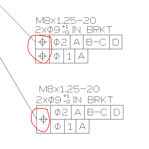
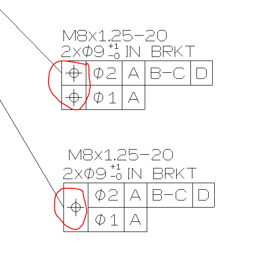
If you have a pattern of M8x1.25-20 screw threads, the center of the pitch diameter of each thread must be positioned relative to the primary (A), secondary (B-C) and tertiary (D) datums within 2mm. The threads must also be positioned relative to the primary datum (A) within 1mm.
[/li]
[li]
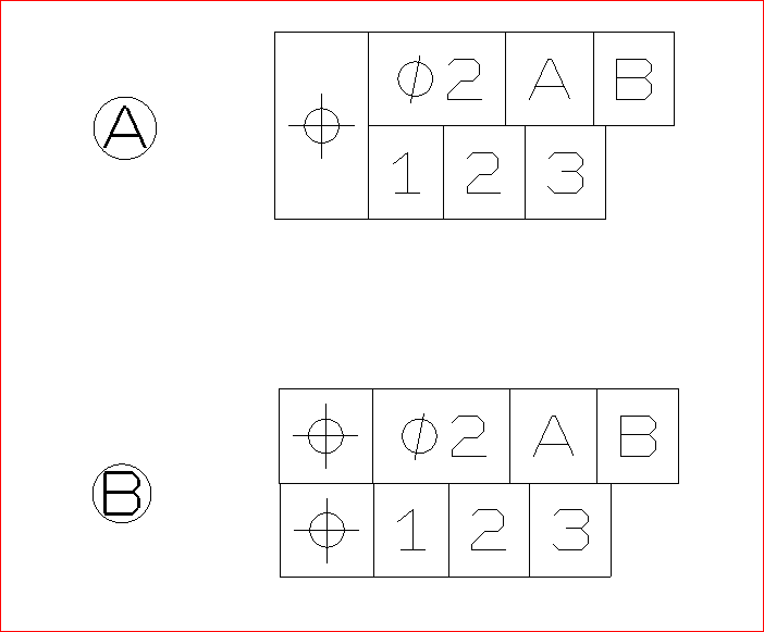
Single position tolerance with two values (composite position tolerance):
A composite position tolerance is a different animal which applies a specifically to pattern of features.
This tolerance would position an entire pattern of screw threads relative to the primary (A), secondary (B-C) and tertiary (D) datums within 2mm. The individual thread pitch diameters in the pattern must then be positioned relative to one another within 1mm. The orientation of the screw thread pitch diameters is also controlled relative to datum A within 1mm.
[/li]
[/ol]
I'll borrow chez311's image for reference.
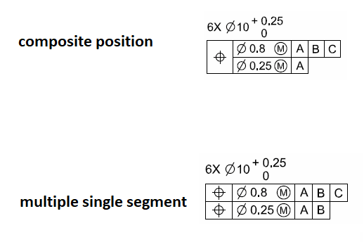
The second type of control can allow the pattern of features to float around a bit, while ensuring that the mating part will still bolt together with the hole pattern. This is helpful in quite a few situations. In the example above, a composite profile doubles the position tolerance on the hole pattern without making the holes bigger on the mating part (and sacrificing crush area).
As others have mentioned, I'm not sure what the 9mm diameter applies to, but maybe in the context of the whole drawing it would make more sense. Also, I assume that this is a hole pattern: If so, the screw callout is missing the number of screws (??x M8x1.25-20).
")