Continue to Site

Eng-Tips is the largest engineering community on the Internet

Intelligent Work Forums for Engineering Professionals

  • Congratulations cowski on being selected by the Eng-Tips community for having the most helpful posts in the forums last week. Way to Go!

GDT V Block Tolerancing 1

Status
Not open for further replies.

njm789

Automotive
Oct 9, 2019
25
Hi,

I want to dimension a v block that will hold a 35mm OD tube in place. The height of the tube is most important. I have seen tapers dimensioned like this, but can this be applied to a v profile or is there a better way of dimensioning this?

Thanks,
Nick

GDT_unekym.jpg
 
Replies continue below

Recommended for you

Make 22.5 (0.886) basic. The rest is good in my opinion.

 
If you want to make it super-clear a profile between points would be also acceptable.
Point A (beginning of the "V" shape) , Point B (ending of the "V" shape)
Profile between A and B.

 
Thanks greenimi! So I don't care about the radius dim as much as the sides of the v holding the tube at a particular height (there will be 3 of these v's in series). Is there a way to keep the sides tight and loosen the tolerance on the radius? I feel the profile tolerance on the v would be too strict on the radius when not needed.
 
njm789 said:
So I don't care about the radius dim as much as the sides of the v holding the tube at a particular height (there will be 3 of these v's in series). Is there a way to keep the sides tight and loosen the tolerance on the radius? I feel the profile tolerance on the v would be too strict on the radius when not needed.

Than maybe another profile between points is needed for the radius alone with bigger tolerance value in the feature control frame.
Left and right "V" shape - profile with smaller tolerance value--one profile control with two leader lines maybe
"V" shape apex -profile with bigger tolerance value (as a stand-alone feature control frame callout)

Again, if you want to be super-clear a profile between points could be used......not sure really needed in this case.

 
If you really want the height of the contact with a 35 mm tube closely controlled then I would dimension it like that. Put a 35mm basic ball gage diameter in the V and dimension from the datum A to the top of the ball. People get all carried away with profile because the standards makers think it's so wonderful but dimensioning for function is much better in many cases. Just like here, nobody cares what the radius is and you really don't care all that much about most of the vee, only the tangent points to the diameter.

----------------------------------------

The Help for this program was created in Windows Help format, which depends on a feature that isn't included in this version of Windows.
 
"Non-uniform" option for me looks like an "overkill" and if the OP is not using 2009/ 2018 then probably is not available for him.

I don't want to get (again) into a lengthy disagreement, but the option with the ball gage is more an inspection method driven approach.
And since each and every inspection method has its uncertainties (are just some form of estimation of the actuals) the gage ball method is no exception.


Thank you all for the information! I am working with 1994 version (LOL) but am currently in the process of updating.
 
greenimi,

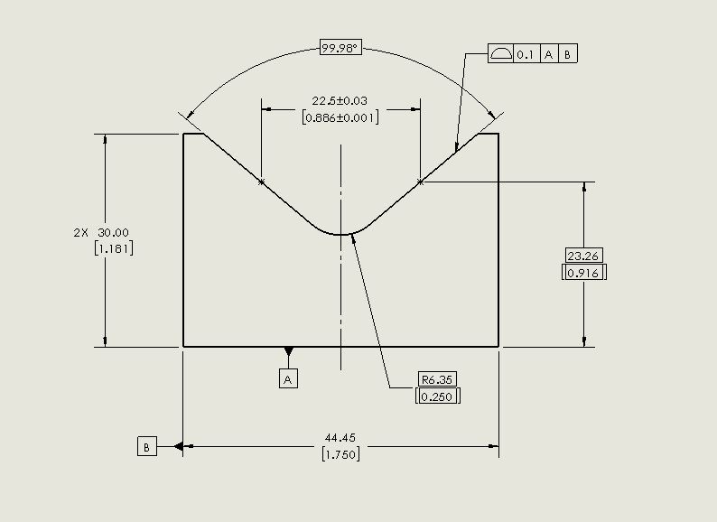
I would say no more overkill than separate profile tolerances. Assuming OP uses Y14.5-2009 or later. If one wants to really simplify it just put 2X profile and 2X leader lines to the pair of inclined faces and make the radius directly toleranced instead of basic. *Edit - I see OP is only on 1994, indeed then non-uniform is not an option directly supported by the 1994 standard. A note could be used, but in that case I would agree is overkill. Separate profile tolerances or the aforementioned directly toleranced radius are the best options.

dgallup,

That really depends on the application, the length of the part and mating part(s), and how precise the mating parts are doesn't it? If the tube which sits in the "V" is relatively short and tightly controlled then sure a gauge ball/pin would work very well. If the v-block is expected to handle several sizes of tube or if the v-block is very long and/or is expected to hold a long tube with some non-trivial amount of size/form/straightness error then profile might be the better choice.
 
I agree with dgallup. I would use a feature simulator and show a dia 35mm diameter basic circle in the V-groove and dimension its location. The inspector will just need a dia 35mm pin (to match the use of the tube) to set in the block to measure the location for acceptance.

It's use is no different than all the other measuring methods and equipment and is a direct indication of what appears to be the stated goal. It could also be inspected with a CMM or by measuring a few hundred surface points and a careful CAD reconstruction.
 
Status
Not open for further replies.

Part and Inventory Search

Sponsor