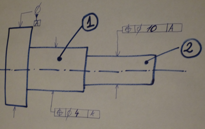
Along the GD&T scheme shown in the picture, an additional functional requirement has been identified by design engineering: Maximum allowable mismatch between features 1 and 2 to be less than 6mm
(maximum allowable distance between the axes of considered features 1 and 2)
The print shall be modified by which option: (choose the best answer; more than one answer could be valid)
a.) Add a lower segment on each position callouts Ø 6 to A and make both positions composite
b.) Add a lower segment on each position callouts Ø 6 to A make both positions multi-single segments
c.) Make OD 1 datum feature D ; add a lower segment within Ø 6 to D on OD 2
d.) Make OD 1 datum feature D; add a lower segment within Ø 12 to D on OD 2
e.) Make OD 2 datum feature D and add a lower segment within Ø 6 to D on OD 1 and make it composite callout
f.) Make OD 2 datum feature D and add a lower segment within Ø 12 to D on OD 1 and make it multi-single segment