Hi,
I have a question regarding interpretation of the drawing below. I understand that this is a basic question, but I have so far had little experience with GD&T...
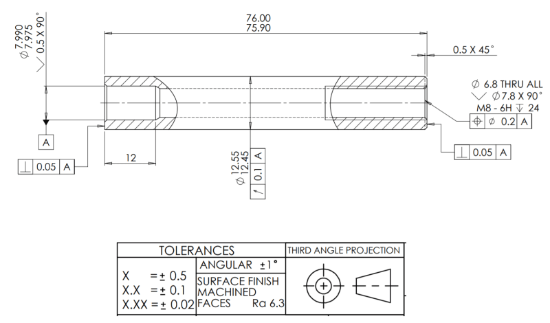
My uncertainty concerns the way in which the form of the end surfaces and length are controlled.
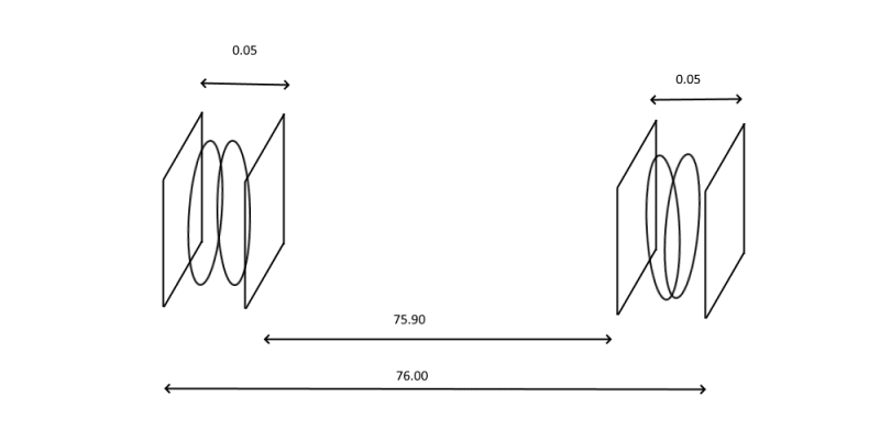
My best interpretation is that length dimension is applied with rule #1 and so the end surfaces must sit within two pairs of planes separated by 76.00 and 75.90 mm. Additionally, these surfaces must be perpendicular w.r.t the A datum. I have drawn what I think this amounts to. Am I missing something? Or is the drawing ill defined?
Any help would be greatly appreciated.
sombreroB
I have a question regarding interpretation of the drawing below. I understand that this is a basic question, but I have so far had little experience with GD&T...
My uncertainty concerns the way in which the form of the end surfaces and length are controlled.
My best interpretation is that length dimension is applied with rule #1 and so the end surfaces must sit within two pairs of planes separated by 76.00 and 75.90 mm. Additionally, these surfaces must be perpendicular w.r.t the A datum. I have drawn what I think this amounts to. Am I missing something? Or is the drawing ill defined?
Any help would be greatly appreciated.
sombreroB