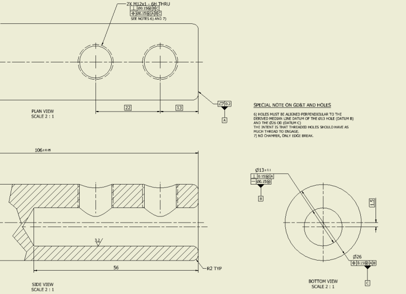
This seemingly simple part is actually a good GD&T head scratcher!
I wouldn't use the two "parallel" axes of the part as a datum because they may not be parallel. They would "fight" with each other.
If the machine shop has a multi-axis machine they could make it with one setup and everything would pretty much be dead-nuts on. The problem may come about when trying to inspect it. If the shop has a Faro/Romer Arm it shouldn't be much of an issue so long as they have a probe tip that can reach down into the blind hole a good ways.
If the shop doesn't have a multi-axis CNC machine nor an inspection arm that is where the difficulty will begin.
If it's the latter situation here's what I would do:
[ul]
[li][/li] If you could add two fairly wide-surfaced opposing flats, sort of like wrench flats, somewhere along the OD of the part (preferably at the end) that would be easier to use as a clocking datum. I say wide surfaced because the wider the surface, the more accurate your clocking will be. So the dimension from flat-to-flat would need to be as small as you can tolerate.
[/ul]
[ul]
[li][/li] This wrench flat clocking datum would be referenced at RFS. You could use this datum for both positioning the offset blind hole and the setscrew holes.
[/ul]
[ul]
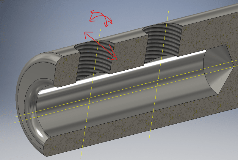
[li][/li] If these wrench flats are not acceptable the only practical way that I know of for you to accurately clock this part in the real world is to think of it as something like a camshaft. Because you're dealing with curved surfaces and not flat perpendicular edges it's really hard to know exactly where the center will be. In the world of engine building there is a process of Degreeing-In the camshaft. Even though the cam and crankshaft have keys which are clocking features, professional engine builders want to know for sure where that cam is installed at as far as degrees in relation to the crankshaft is concerned. The way they do this is by screwing in a hard stop into the spark plug hole of the #1 cylinder. Then they install a degree wheel onto the front of the crankshaft. They rotate the engine forward until the #1 piston hits the hard stop and set the degree wheel to zero. Then they rotate the engine backward until the #1 cylinder hits the hard stop again and put another mark on the wheel. Then they divide those degrees in half to determine exactly where Top Dead Center is on the #1 cylinder. Then they rotate the crank to this halfway mark. Then they reset the degree wheel so that the pointer is now pointing at zero on the degree wheel. Now that they know where Top Dead Center is they can use an indicator to start checking the valve lift figures against the camshaft spec sheet and advance the cam as required. It would be helpful to watch a YouTube video to understand the process.
[/ul]
[ul]
[li][/li] So if you're using the method above, the only way I know of for checking for "Top Dead Center" or TDC on this part would be to chuck the part in a four-jaw chuck and adjust it till the center blind hole runs true with zero runout (what a pain). Then use a dial indicator along the OD and the Finding TDC Routine to know exactly when you're at the thickest upper part of the shaft.
[/ul]
[ul]
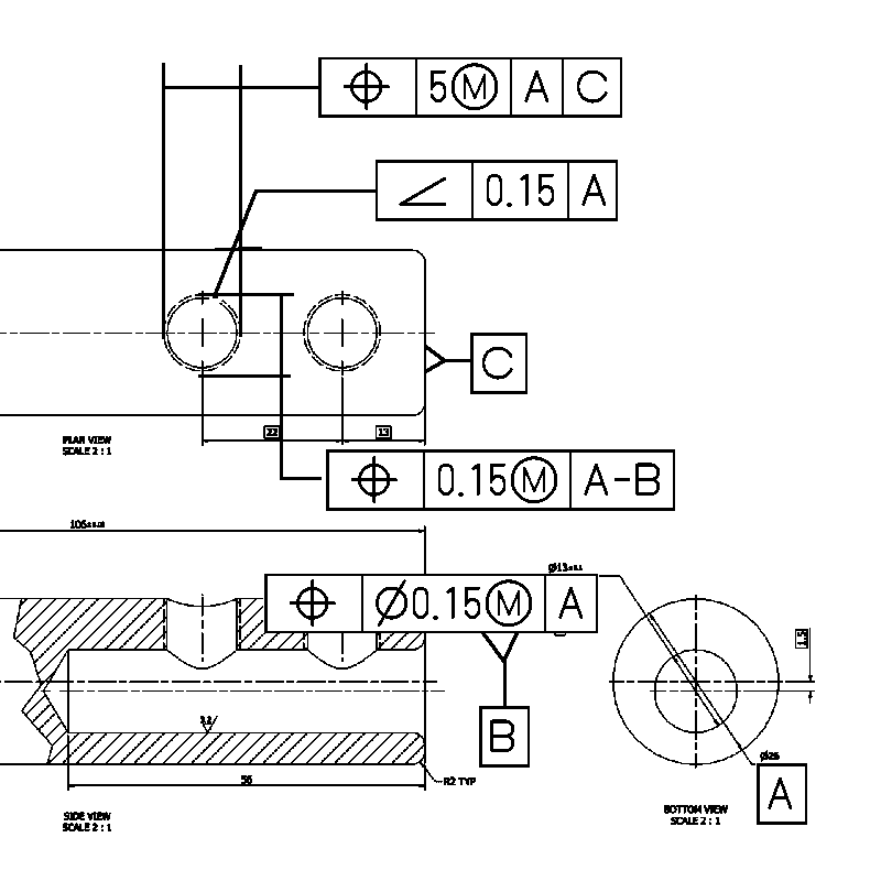
[li][/li] I wouldn't use perpendicular, parallelism, or angularity to control the orientation of the setscrew holes. They're just setscrews. It's not going to make or break the functionality of the assembly if they're minutely tilted. What's more of a concern is that they might loosen so just use some threadlocker. Just use position because position does also control perpendicularity.
[/ul]
[ul]
[li][/li] The other thing to note is that you have the position of the threads at MMC. It might be easier check the threaded holes at RFS. Also, it might be easier to add the note MINOR DIA below the thread position Feature Control Frame so that they can just check the ID of the threaded holes rather than the actual pitch diameter of the threads.
[/ul]
Hope this helps.