Continue to Site

Eng-Tips is the largest engineering community on the Internet

Intelligent Work Forums for Engineering Professionals

  • Congratulations KootK on being selected by the Eng-Tips community for having the most helpful posts in the forums last week. Way to Go!

FRTZF TOP calculating 2

Status
Not open for further replies.
Replies continue below

Recommended for you

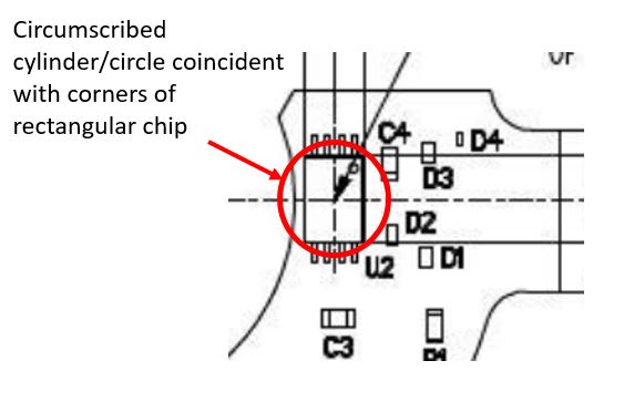
greenimi - could it not be as simple as this to create a circular feature? Just like Fig 4-35 (b) but instead being coincident to the corners of the rectangular chip. I know its technically overconstrained with 4 points instead of 3 but one could specify the smallest circumscribed cylinder/circle which all 4 points lie on or within - or something similar.

circumscribed2_ikpr1j.jpg
 
Talking about loud, probably a better approach would be a composite all around profile where the height and width of the chip would be basic (upper segment to A, B and C and lower to be datumless).

Or if position wanted to be used then composite position for EACH of the height 4.40±0.10 and width 3.00±0.1 with SIM REQT under FRTZF (datumless or with A primary—to keep both parties happy[bigears])


Chez311,
How to get a repeatable and reproducible axis/ centerplane from a circle / cylinnder thru 4 points? That's my question.
 
greenimi,

I was under the assumption that the attempt was to create a scheme where the outer profile of each chip could rotate freely with respect to its nominal center. I don't think that either your all around profile or position allows this - wouldn't they both put orientation constraints on the outside profile of the chip? Not that I have an inherent issue with this, I was just running with that initial assertion - it would alleviate the issue of having to specify a non-standard note or irregular FOS.

Additionally I don't think that either allows the simultaneous radial "dilation" I mentioned earlier. As of yet I don't know of a method that would allow this - again not that I have an inherent issue with this either, I am just genuinely very curious whether someone can come up with a solution that does this.

3DDave 9 Dec 18 15:51 said:
if the whole pattern of sensors shifts as a block it will increase the difference in pickup location as the entire group drifts off axis, so I fail to see the benefit to a composite tolerance.

Regarding the application of composite tolerance I reference the above from 3DDave. I know there has been much discussion here about the merits of datumless control frames, but I think that in this case a Multiple Single Segment with [A|B] in the lower frame would be more appropriate to allow rotation of the pattern but not let it shift off axis as composite tolerance would do.

greenimi 11 Dec 18 17:25 said:
How to get a repeatable and reproducible axis/ centerplane from a circle / cylinnder thru 4 points? That's my question.

If you are asking in regards to geometry - its just as I said, I was thinking with a note stating "smallest circumscribed cylinder/circle which all 4 points lie on or within" or something to that effect to prevent overconstraint - as in the circumscribed feature would contact at least 3 points. Do you see an issue with this? I know that perhaps the corners are not the best features to utilize but I figured it would provide a reasonable estimation of the center.

If you are asking in regards to practicality for inspection, I would imagine a scanning head or imaging system could handle it.
 
Chez311,
chez311 said:
I was under the assumption that the attempt was to create a scheme where the outer profile of each chip could rotate freely with respect to its nominal center

Okay, I understood.

pmarc said:
.......is that by controlling position of the "centers" of the chips (even if we assume that the drawing clearly defines what the "center" really means) the chips are allowed to rotate freely about their individual "centers". My feeling is that this is not acceptable from the design standpoint.

I was under the impression that the rotation is not acceptable from the design point of view (based on just reading and understanding this discussion). I might be wrong.

chez311 said:
but I think that in this case a Multiple Single Segment with [A|B] in the lower frame would be more appropriate to allow rotation of the pattern but not let it shift off axis as composite tolerance would do.

Can you accomplish the same thing by using composite position (instead of multi single segments as you suggested) and FRTZF having a complete datum A, B and C in this order of precedence?
 
greenimi - composite allows controlling orientation in the lower segments, not controlling location relative to the referenced datum features.

Also - there are only 3 points in this case, so a center is easy to find, once the points are defined.
 
greenimi,

The direct response to that quote from pmarc is what I was going off of.

3DDave 9 Dec 18 19:52 said:
pmarc - the chips frequently have the sensing element in the nominal center and the orientation may not be critical. It is likely that they would be controlled by default with a general angle tolerance as applied to angles defined per 1.4(i). If they were given separate angular and radial position tolerances, as I suggested was the most likely necessary control for the function, then orientation would be a fallout.

However the second half of that seems to conceed that it may be acceptable to constrain orientation as a result of either of these controls (your all around profile or separate length/width position).

Taking that a bit further, this is essentially an assembly and the method of attachment should be considered. If these chips are through-mount then the holes will only permit so much rotation, if this is a surface mount component surely there should be a constraint on orientation to ensure the pins/leads make acceptable contact with the mating leads on the board.

These two points seem to suggest that perhaps its not worth the complexity of trying to either utilize a custom note or create an irregular FOS from the corners.

Also ditto what 3DDave said about composite vs. multiple single segment. I believe the location of the pattern (or the CONSISTENT location of each feature of the pattern - ie: the features are as close to equidistant from the center and each other as possible) back to the central axis of the board is more critical in this instance than the orientation of the pattern.
 
3DDave,

What do you think about my above statement due to your previous comment as well as the possible assembly methods that a custom note/irregular FOS is maybe not worth the complexity?

Also I apologize for repeating it once again but do you have a method of allowing the simultaneous radial dilation I keep mentioning? I realize after re-reading your response that this may not have been your intent because although I took your statement "separate radial and angular position tolerances" to mean that you wanted to allow simultaneous radial movement of the components (the tolerance zones could move away from or toward the board's central axis together/simultaneously) your following comment about "limiting radial travel to a narrow band" suggests this is not the case. Regardless I'm still interested if it is possible.
 
All: Is the OP (SeasonLee) still following this thread?

Certified Sr. GD&T Professional
 
chez311 - probably a note or acceptance procedure, if "Fig. 7-29 Bidirectional Positional Tolerancing, Polar Coordinate Method" is not tight enough/ too tight.

I know the same base question has been asked before - "How can multiple dimensions/features be controlled to be the same in a narrow range of each other within a much larger range overall?"

I don't recall a particular answer to it.
 
mkcski said:
All: Is the OP (SeasonLee) still following this thread?
I'm here and always enjoying the different comments from different view points. Thanks all you guys.

Season
 
I know the same base question has been asked before - "How can multiple dimensions/features be controlled to be the same in a narrow range of each other within a much larger range overall?"

Here are two previous discussions on the subject:
thread1103-418930
thread1103-432346


pylfrm
 
pylfrm,

Thanks for the linked threads - that a very interesting workaround and it pretty much accomplishes what I was referring, not necessarily one that I would want to use unless I had to but definitely one for the toolkit. Of course, it may become mostly obsolete with the inclusion of the dynamic profile tolerance however if that applies only to profile it may still be useful for position (as in this case).
 
All,

I feel like after all the discussion, OP deserves a workable solution - what does everyone think about the below scheme? I have applied it to the width/length instead of the center per the above few comments - in summary I don't think its worth the trouble to apply position to the center of the chip, and while the sensing element may not care, depending on the assembly method rotation likely needs to be constrained.

I think it accomplishes most of the functional requirements of the chips as far as I can tell. Theres no dynamic/simultaneous dilation either (ie: allowing the tolerance zone for the center of the chips to move simultaneously towards/away from the board center axis) however I think thats added complexity that shouldn't be included unless absolutely necessary. Of course the designer would have to determine if the allowable amount of rotation by this method is acceptable.

Single Segment Radial Position Tolerance (applied to width 3.00 dim)
3x 3.00+/-0.10
⊕0.20 [A|B]​
*I don't think C is necessary here in the DRF as its limited in rotation by the angular tolerance. It could be added but would result in very little difference in the allowable tolerance.

Multiple Single Segment Angular Position Tolerance (applied to length 4.40 dim)
3x 4.40+/-0.10
⊕0.40 [A|B|C]​
⊕0.20 [A|B]​
 
Or going by an earlier suggestion, profile could be utilized - requiring basic dimensions on the width/length as well distance to the edges of the chip:

Multiple Single Segment Profile Tolerance (applied 3x all-around each chip)
(profile)0.40 [A|B|C]
(profile)0.20 [A|B]
 
Status
Not open for further replies.

Part and Inventory Search

Sponsor