Continue to Site

Eng-Tips is the largest engineering community on the Internet

Intelligent Work Forums for Engineering Professionals

  • Congratulations KootK on being selected by the Eng-Tips community for having the most helpful posts in the forums last week. Way to Go!

FRTZF TOP calculating 2

Status
Not open for further replies.
Replies continue below

Recommended for you

Composite tolerance feature control frames are intended to release some degrees of freedom - not all of them. I think the callout is essentially nonsense and should reference at least the primary datum.

Aside from that, I didn't go through the trigonometry to figure out if your calculations carry enough decimal places. Also, as noted in a previous post, sticking to a particular orientation of coordinate system excludes acceptable solutions. I posted a paper gaging spreadsheet that includes that calculation.
 
Thank you 3DDave.

3DDave said:
I posted a paper gaging spreadsheet that includes that calculation
Would you please advise the link.

Season
 
3DDave said:
Composite tolerance feature control frames are intended to release some degrees of freedom - not all of them. 

I take it as a general statement, so I have to ask... What makes you think the statement is correct?
 
pmarc - I should have added a 10000 word essay explaining every possible condition. I'll get right on that.

In the mean time, within the context of this particular problem, is there any suspicion that the chips will no longer lie in plane such that removing the primary datum helps describe a desirable outcome?
 
I am curious as well 3DDave. While it seems irregular to have no datum references in the lower frame I'm not clear on why it would be illegal per the standard. Would you say the same about a multiple single segment control frame?

The thing that bothers me more is the application of a position control to the theoretical center of the chip by way of the intersection of two center lines. I understand the intent and that maybe its desired to control the width/length simultaneously (instead of a separate position control on each) but is this the best way to go about it? It occurs to me that going strictly by the standard this wouldn't be allowed.
 
I didn't say "illegal." As to this particular application I am more curious about the probability that this is a Brushless Motor controller sensor board and that there should be different tolerances for radial and angular placement rather than a diameter; more than that, if the whole pattern of sensors shifts as a block it will increase the difference in pickup location as the entire group drifts off axis, so I fail to see the benefit to a composite tolerance.

It would be interesting to see the application note for the part to see the recommendation for dimensioning and tolerancing.
 
3DDave said:
pmarc - I should have added a 10000 word essay explaining every possible condition. I'll get right on that.

There are questions/threads where, for different reasons, it is indeed quite difficult to give a precise answer without "a 10000 word essay explaining every possible condition", as you put it, but this is definitely not one of these cases. You would avoid my question simply by not making this general, and in my opinion incorrect, statement.

As for the particular application, one of the problems I see (regardless if lack of A in the lower segment adds any value to the product or not, and regardless if the position tolerance zone should be cylindrical or have different values in radial and circumferential directions) is that by controlling position of the "centers" of the chips (even if we assume that the drawing clearly defines what the "center" really means) the chips are allowed to rotate freely about their individual "centers". My feeling is that this is not acceptable from the design standpoint.
 
pmarc - the chips frequently have the sensing element in the nominal center and the orientation may not be critical. It is likely that they would be controlled by default with a general angle tolerance as applied to angles defined per 1.4(i). If they were given separate angular and radial position tolerances, as I suggested was the most likely necessary control for the function, then orientation would be a fallout. I'm certain that the tolerances weren't allocated based on function just from the clumsy and unhelpful exclusion of the primary datum in the lower segment and the unlikely possibility that the tolerance zones would be diametral in nature.


Now I feel chastised and will never write this exact general statement again, even when in context it makes complete sense. Excuse the numerous examples in the standard that show configurations just like this that always repeat at least the primary datum. They didn't intend to give any such impression in spite of allowing the option. But maybe if the sensors were coaxial? There are examples of that. Examines drawing. Sees they are not.

So I'll go back and change it to: except in the cases of coaxial holes it is generally not useful, even though it is completely legitimate, to omit all datum references in the ... and so forth.

Here's hoping the next version will feature a non-coaxial no-datum lower composite tolerance diagram so the OP can look up the official "Means this." It's obviously what they intended.
 
I do learned more than I expected here, at least I learned something can be done to make an improvement on the design intent.

Let's back to my question, I still need to know if I'm right on the FRTZF TOP concept and its calculating.

3DDave
I can't find out the paper gaging spreadsheet that you posted, would you pls post it again. Thanks lot.

Season

 
3DDave said:
So I'll go back and change it to: except in the cases of coaxial holes it is generally not useful, even though it is completely legitimate, to omit all datum references in the ... and so forth.

So it looks like the composite callout, as shown in the attached picture, would not be useful.

In other words, if the sole function of the pattern of the holes was to reduce the weight of the part, the holes should be perpendicular to A within the FRTZF tolerance? Am I getting your statement correctly? Or maybe it would be just useful in this very case, but it still wouldn't be "generally" useful?
 
SeasonLee,
The lower segment of the composite callout, regardless if it contains a reference to datum(s) or not, always controls spacing between the centers of the chips. This means that all 3 centers must fall simultaneously within a pattern of 3 cylindrical tolerance zones of diameter 0.20, but it is not important how the 3 tolerance zones are oriented to any datum(s).

So to calculate the spacing all you have to do is to find basic linear distance between the centers of the tolerance zones (based on the basic linear and angular dimensions given on the drawing) and add 0.20 (for maximum spacing) or subtract 0.20 (for minimum spacing) to/from that. Note: This will give you extreme spacing values for each individual pair of centers, but I don't think that based on that calculation you will be able to say all 3 centers can simultaneously be that far or that close from/to each other.
 
Thanks for your input, pmarc.

Shift could happened as long as the center of each chip within its own Ø0.20 cylindrical tolerance zone, am I right?

Season
 
pmarc - an interesting contrived example. So if the part has to be rotated 45 degrees about the vertical axis to see that the holes meet that requirement, that's what you would expect from what fabrication process? Wouldn't a separate LMC requirement be the preferred choice for controlling remaining thickness explicitly? Why yes, LMC would. But for some reason that's not what's used in the Feature Control Frame. Why not?

Am I getting that a defective description of a realizable part is the basis for your argument?

Looking closer it appears that there was a datum reference that was erased from the figure; using Paint or Photoshop leaves marks.
 
pmarc said:
I don't think that based on that calculation you will be able to say all 3 centers can simultaneously be that far or that close from/to each other.

You are very correct. It's not a good method. I have uploaded a copy of a GeoGebra** diagram that demonstrates this. If two of the features are as close to each other as possible, the allowable maximum distance from each to the third is only 0.037 over the nominal, not the 0.200 as suggested. This does assume that they are oriented to datum A, as I haven't done out-of-plane calculations which could allow at least one pair to be at the 0.40 limit projected to datum A. Roughly it's a bit over 10 degrees of rotation out-of-plane.

**Free software.
 
 https://files.engineering.com/getfile.aspx?folder=ae5b0875-f162-4728-82f3-72e7c7effbf2&file=three_points.ggb
Season,
Shift may happen as long as all 3 centers are within their respective tolerance zones simultaneously.

3DDave said:
So if the part has to be rotated 45 degrees about the vertical axis to see that the holes meet that requirement, that's what you would expect from what fabrication process?
All I want to say by applying this kind of composite callout is that I do not care about perpendicularity of the holes relative to datum plane A and about location of the holes relative to B as much as about spacing between the holes within the pattern. Granted, the datumless lower segment is probably more challenging to inspect than the lower segment referencing A primary, but this does not mean the part has to be rotated 45 degrees about the vertical axis to check this requirement.

3DDave said:
Wouldn't a separate LMC requirement be the preferred choice for controlling remaining thickness explicitly?
Not sure if you noticed, but I explicitly stated in the text right next to the FRTZF that it could be defined at LMC basis. Also, not sure what you mean by "a separate LMC requirement".
 
pmarc said:
and regardless if the position tolerance zone should be cylindrical or have different values in radial and circumferential directions) is that by controlling position of the "centers" of the chips (even if we assume that the drawing clearly defines what the "center" really means) the chips are allowed to rotate freely about their individual "centers".
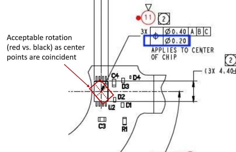
Pmarc,
May I ask, why "the centers of the chips" are allowed to rotate freely about their individual centers and not within the tolerance offered by the PLTZF (Ø.040)? Just asking to refresh my knowledge or to learn something I had no idea I did not know.
Thank you

 
Season/3DDave,
Since nobody posted it, if I'm not mistaken I think the paper gauge spreadsheet/discussion referenced was this ( right? It was actually in a thread started by Season.

greenimi,
I'm not going to speak for pmarc but I just want to say you may have mis-read that statement. It reads the CHIPS (not the center of the chips) can rotate about their individual centers - ie: since the position control applies to only the center of each chip instead of the outside profile, the outside profile can rotate freely. Pmarc feel free to correct me if I'm wrong.

chip_rotation_pkydmr.jpg


pmarc (10 Dec 18 12:12) said:
Granted, the datumless lower segment is probably more challenging to inspect than the lower segment referencing A primary
Thats an interesting point that I hadn't considered - that the reduction of requirements (removal of datum feature in a DRF and resulting DOF) might actually make a part more difficult to inspect. Definitely something I'll have to keep in mind in the future.
 
Chez311,
So, what should lie within the cylindrical TZ of Ø.020--in your embeded picture? Horizontal centerplane ? Vertical centerplane? Both?
If both, what that means? An axis driven by both centerplanes?

Not sure I understand (DOF versus grouping tolerance zones for FRTZF)

Editted for typo Ø.020 versus Ø0.20
 
greenimi,

I was just trying to clarify the statement - I stand by my original statement further up in the thread that I don't think that this practice is kosher. The position tolerance should really be applied to a feature of size - I don't think its okay to apply a position tolerance to a theoretical plane/axis nevermind another theoretical axis/point formed by the intersection of other theoretical features.

My guess would be the intent was to control the axis formed by the intersection of the two center planes. These features would have to be better defined in order for me to get behind this method.
 
Status
Not open for further replies.

Part and Inventory Search

Sponsor