Continue to Site

Eng-Tips is the largest engineering community on the Internet

Intelligent Work Forums for Engineering Professionals

  • Congratulations cowski on being selected by the Eng-Tips community for having the most helpful posts in the forums last week. Way to Go!

FoS perp, flat and parallel help

jamiethekiller

Mechanical
May 2, 2025
3
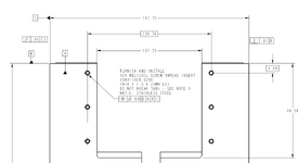
I have a big weldment. All sides are to be machined and held flat ~.01"(still working that out). From one long end to the other i was going to hold that dimension as a datum and then hold the rectangular hole pattern to that dimension. Doing it this way i can keep the hole pattern 'symmetric' to the overall width dimension(+/- .01") instead of whats historically been done(which is datum on one side and then dimensioning from that datum.

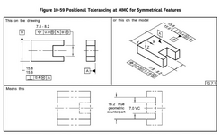
My problem comes in then, how do i communicate that i want the sides flat and parallel to each other and perpendicular to the top surface as well? At first i thought i would use Flatness on the width FoS but that doesn't seem to commincate that. Can i have my overall width dimension be a datum([-C-]) and THEN have one of those surfaces of that FoS width be a datum as well to communicate flatness and parallelism? Figure 10-59(2018) intrigued me but i couldnt' find anything about the perpendicular callout on the FoS in the standard. Its near the same shape(dimensions wildly different) but the bolt pattern follows the slot.

I can go back to the tried and true way and just dimension from one surface and 'live' with the bolt pattern potentially not being 100% symmetric(its not that big of a deal) but i've also come across this same kinda exercise on other parts so looking for clarity.

tldr:
need help identifying Datums so that my bolt pattern is symmetric to the overall width of the part but each side of the width needs to be flat/parallel to each other and then perpendicular to another top surface.

Thanks
 

Attachments

  • Screenshot 2025-05-02 124032.png
    Screenshot 2025-05-02 124032.png
    37.4 KB · Views: 7
Replies continue below

Recommended for you

With a directly toleranced width and rule #1 of Y14.5 intact, you don't need to worry about flatness of each side unless flatness needs to be tighter than the size tolerance, and with some very rare exceptions as in post #13 Here, same goes for parallelism.

Feature of size perpendicularity that you found in fig. 10-59 controls the perpendicularity of the center plane of the width. Since it is referenced at MMC, it can be interpreted that the Related Actual Mating Envelope (see Related AME in fig. 3-1) cannot exceed the value of 15.8 (MMC limit) + 0.4 = 16.2. Another way to put it is that there is a Virtual Condition Boundary (see Fig. 5-17) of 16.2 for the perpendicularity at MMC requirement.
i saw that post when doing my searching and it really got me thinking(and confused).

in this case. the overall width can be +/- .01. So the overall rectangle can be a parallelogram with .01 to the top left of the part and .01 to the bottom right of the part. I would rather keep the overall width +/- .01 but keep the parallelism between the two parts much tigher(say .01 or even .005). I can't figure out how to do that with my overall width being a FoS datum. I was also considering putting a perp tolerance of 0 MMC on the overall width dimension. But the bonus tolerance on something like that could really get me tilted, right?

But i'd prefer to keep my width a datum so i can have multiple different linear hole patterns be symmetric to that overall width.

Does that make sense?
 
If you want them to be parallel to each other, make each of them a datum feature with a datum feature symbol and set each of them parallel to the other with a parallelism geometric tolerance control in the feature control frame.

If they need to be flatter than the parallelism limit use a flatness geometric tolerance control in a feature control frame for each surface.

If they need to be perpendicular to the top surface then use a perpendicularity geometric tolerance control in a feature control frame attached to the surfaces and use a datum feature symbol to identify the top surface as the intended reference. Or, you can add the perpendicularity geometric tolerance control in a feature control frame attached to the width dimension to indicate that the control applies to the width as Figure 10-59 shows. The latter will not control flatness of the individual surfaces or perpendicularity of the individual surfaces to the top surface.

The dimension is not a datum feature, but the datum feature symbol can be associated with the width dimension.

I think that clears some things up in my head for me.

Can i have the width be a datum(in this case -C-) and also each surface be their own datum?

so the width be C
the left surface be D
and the right surface be E?

I can set D to be perp to B and A
I can set E to be parallel to D

So Datum C would just control my symmetric dimensions(several bolt patterns)
and Datum D and E would control the form of those two surfaces?
 
I don't know what you are assigning A and B to, but ...

Datums D and E on the side faces would be the references for the control the parallelism of the surfaces on the opposite side from them.

Can i have the width be a datum(in this case -C-) and also each surface be their own datum?

Yes.
 

Part and Inventory Search

Sponsor