I'm looking for a gut check on my interpretation of the requirements for connection design as per Clause 27 (CSA S16).
Simple structure using LD MRF (Rd = 2.0, Ro = 1.3) designed to post-disaster (IE = 1.5) but in a relatively low seismic zone. All connections need to be bolted, no field welding.
TL;dr - With capacity designed moment connections for members under very small loads, can the design force applied to the connection be limited to the factored seismic force under RdRo = 1.0? Or are you always forced to design to the probable moment capacity of the beam when using the "pre-approved" moment connections from CISC's DM7?
For the design of the moment connection, Clause 27.4.4.1 gives me three choices:
1. Design to S16's requirements (Clause 27.4.4.2)
2. Design to the CISC "pre-approved" moment connections from DM7
3. Test the proposed connection using Annex J
Option #2 is straight forward, but seems to imply that the moment connection needs to be designed for the probable moment resistance of the beam. The DM7's examples are all positioned to design to the probable moment resistance of the beam. Ok. I get it...capacity design -- connection as strong or stronger than the likely maximum resistance supplied by the beam. I can do bolted flange plates with the plates welded to the column in the shop.
S16's requirements in Clause 27.4.4.2 indicate that the moment connection needs to incorporate beam flanges directly welded to the column flanges. This is not possible in my situation since the connections need to be bolted. So, Option #1 would technically be out of reach for me. But, further on the clause mentions the required connection resistance:
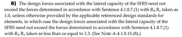
For my chosen W12 beam, the moment resistance under the factored seismic load combination is at ~16%. Even under the elastic earthquake load (Rd Ro = 1.0), the moment resistance utilization is still ~50%. Where I am getting kind of jammed up is that this simple structure really has very little load on it, but the wording of the clauses implies that the connection design still needs to be designed for the maximum possible beam moment...even if this is substantially greater than the loads under the elastic earthquake load. I'm wondering if there is a general "bail-out" clause somewhere that I'm missing. I see that Clause 27.1.2.2 mentions that the force "need not exceed those determined with RdRo = 1.0". Reading this clause now (...yes it's 1:15AM), it does mention "...and connections..." and I wonder if this is the correct interpretation ===> run the factored seismic load case with Rd Ro = 1.0, IE = 1.5 to check connection strength, run the elastic earthquake load case (Rd Ro = 1.0, IE = 1.0) to check drift of the structure ... repeat for the 5% in 50 year earthquake because it's post-disaster...
Simple structure using LD MRF (Rd = 2.0, Ro = 1.3) designed to post-disaster (IE = 1.5) but in a relatively low seismic zone. All connections need to be bolted, no field welding.
TL;dr - With capacity designed moment connections for members under very small loads, can the design force applied to the connection be limited to the factored seismic force under RdRo = 1.0? Or are you always forced to design to the probable moment capacity of the beam when using the "pre-approved" moment connections from CISC's DM7?
For the design of the moment connection, Clause 27.4.4.1 gives me three choices:
1. Design to S16's requirements (Clause 27.4.4.2)
2. Design to the CISC "pre-approved" moment connections from DM7
Option #2 is straight forward, but seems to imply that the moment connection needs to be designed for the probable moment resistance of the beam. The DM7's examples are all positioned to design to the probable moment resistance of the beam. Ok. I get it...capacity design -- connection as strong or stronger than the likely maximum resistance supplied by the beam. I can do bolted flange plates with the plates welded to the column in the shop.
S16's requirements in Clause 27.4.4.2 indicate that the moment connection needs to incorporate beam flanges directly welded to the column flanges. This is not possible in my situation since the connections need to be bolted. So, Option #1 would technically be out of reach for me. But, further on the clause mentions the required connection resistance:
To me this implies that there is a "bail-out" to allow the designer some reprieve from designing to the full capacity of the beam if that value exceeds 2 x seismic load."Beam-to-column connections shall have a moment resistance equal to [probable moment resistance], except that, when the controlling limit state is ductile, the moment resistance need not exceed the effect of the gravity loads combined with the seismic load multiplied by 2.0"
For my chosen W12 beam, the moment resistance under the factored seismic load combination is at ~16%. Even under the elastic earthquake load (Rd Ro = 1.0), the moment resistance utilization is still ~50%. Where I am getting kind of jammed up is that this simple structure really has very little load on it, but the wording of the clauses implies that the connection design still needs to be designed for the maximum possible beam moment...even if this is substantially greater than the loads under the elastic earthquake load. I'm wondering if there is a general "bail-out" clause somewhere that I'm missing. I see that Clause 27.1.2.2 mentions that the force "need not exceed those determined with RdRo = 1.0". Reading this clause now (...yes it's 1:15AM), it does mention "...and connections..." and I wonder if this is the correct interpretation ===> run the factored seismic load case with Rd Ro = 1.0, IE = 1.5 to check connection strength, run the elastic earthquake load case (Rd Ro = 1.0, IE = 1.0) to check drift of the structure ... repeat for the 5% in 50 year earthquake because it's post-disaster...