Tek-Tips is the largest IT community on the Internet today!

Members share and learn making Tek-Tips Forums the best source of peer-reviewed technical information on the Internet!

  • Congratulations JStephen on being selected by the Eng-Tips community for having the most helpful posts in the forums last week. Way to Go!

Fluid Head

Status
Not open for further replies.
• Is there an analytical solution which can be used to compute the head [H].

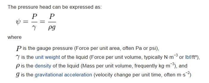
The Total Head is the sum of pressure head - p / γ, velocity head - v2 / 2 g, and elevation head - h. For flow in a pipe, h is usually taken to be the elevation of the centerline of the pipe before it enters the main pine.


• What are the main parameters which controlling the head [H].

The main parameters will be the pressure head and velocity head.

• Does the head [H] vary along the surface of the fluid inside the main pipe? For example is the head at point 1 equal the head at point 2 and 3?

If the exit pipe has more capacity than the main pipe. The level will fall off as it enters the exit pipe. Point 1 will have a slightly higher level than point 2, which will be slightly higher than point 3.

• In case the rotating pipe stops rotating, would it influence the head [H].

The rotating pipe will tend to cause centrifugal flow in the main pipe which will cause the outer edges of the pipe to have higher water levels. The water levels will vary with the centrifugal forces imparted.

• Is the velocity profile will have symmetric streams inside the main pipe? Velocity profile 1 and velocity profile 2, are they symmetrical. If 2 velocity sensors [Doppler] installed at point 4 and 5 would they give similar mean velocity.

Probably will be very close.
 
This has been seen before but I can't find the post. Now looks like a student question....

Identical file, identical questions.

Remember - More details = better answers
Also: If you get a response it's polite to respond to it.
 
Joined on January 15, 2016. What's with the .docx attachments recently?

Piping Design Central
 
Dear all thanks a lot for your quick response ,
LittleInch , yes you are right , I posted it few day ago here , however by unknown reason my account was blocked.
Dear bimr , thanks a lot , your answers are great. However there is small misunderstanding, the fluid flows from the bottom of the main pipe , then flows out via the exit pipe. you used that the fluid head can be computed by using Bernoulli equation [The Total Head is the sum of pressure head - p / γ, velocity head - v2 / 2 g, and elevation head - h], it is ok, but what about the discharge of the exit pipe ? , we must count for it right ?
If flow right is known and the diameters of the 2 pipes , how would the fluid head [as indicated in the figure] be calculated? pressure head is function of the fluid head right, the tope part of the main pipe is open to the atmosphere and the exit pipe too.
Can you please explain to me in more details how you would compute the fluid head ?
 
The exit loss from the horizontal pipe into the vertical main pipe is 1* v2 / 2 g.

Assume your control point is a horizontal pipe located just before the horizontal pipe enters the main vertical pipe.

Pressure Head (measured at the control point):

press_rq14rr.jpg


Velocity (Head measured at the control point):

vel_umny4t.jpg


Elevation Head (measured at the control point):

For flow in a pipe, h is usually taken to be the elevation of the centerline of the pipe.
 
Probably removed the first time as it looks like a student post, is it?

It is a capital mistake to theorise before one has data. Insensibly one begins to twist facts to suit theories, instead of theories to suit facts. (Sherlock Holmes - A Scandal in Bohemia.)
 

bimr thanks a lot , i really appreciate your help ,,
Artisi , it is not student home work , :)
 
Status
Not open for further replies.

Part and Inventory Search

Sponsor

Back
Top