Tek-Tips is the largest IT community on the Internet today!

Members share and learn making Tek-Tips Forums the best source of peer-reviewed technical information on the Internet!

  • Congratulations JAE on being selected by the Eng-Tips community for having the most helpful posts in the forums last week. Way to Go!

Flow inconsistence

Thuba

Chemical
Joined
Nov 21, 2024
Messages
67
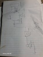
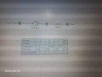
l have a pump rated at 4m3/h and 35m head. lt pumps edible oil through an economizer and the to dearator with some nozzles. From the dearator there is another pump feeding a vessel (rated 9m3/h and 40m head) and there is a flowmeter reading 1800L/h (1.8m3/h). Some how the dearator gets empty or starved with oil. My question is how so as the dearator pump is just pumping 1.8 m3/h from the dearator, while the one feeding it is feeding at a rate of 4m3/h. see attached schematics
 

Attachments

  • 20250623_003005.jpg
    20250623_003005.jpg
    1 MB · Views: 8
how so as the dearator pump is just pumping 1.8 m3/h from the dearator, while the one feeding it is feeding at a rate of 4m3/h.
IMO ,the answer is simple . The capacity of pump 101 could be 4 m3/hr but still the flow is less than 1.8 m3/hr or the flow is more than 1.8 m3/hr.
I will suggest you two alternatives,
-provide frequency converter for pump 102 modulated with the oil level at the deaerator.
- check if possible to lift the deaerator above the vessel and delete pump 102
You may also consider to provide more details to get better responds
 
Last edited:
I take that all of your flows and heads have been corrected for SG and viscosity.
I agree with HT, you are either not getting 1.8 out of 101 or the measured flow is wrong.
 
This is why you don't double post. There are some similar replies in the chemical forum.

This was mine

What type of pumps are these?

PD type pumps will generally pump at a fixed flow, +/- 10%.

Centrifugal pumps generally provide a fixed differential head +/- 15% from your duty point.
T
The duty point flow is only one point on a curve. What flow you actually get is dependant on your downstream frictional and head losses.
 
I take that all of your flows and heads have been corrected for SG and viscosity.
I agree with HT, you are either not getting 1.8 out of 101 or the measured flow is wrong.
yes we use a flowmeter dedicated to our product, soybean oil corrected for S.G. and viscosity at given temperature
 
This is why you don't double post. There are some similar replies in the chemical forum.

This was mine

What type of pumps are these?

PD type pumps will generally pump at a fixed flow, +/- 10%.

Centrifugal pumps generally provide a fixed differential head +/- 15% from your duty point.
T
The duty point flow is only one point on a curve. What flow you actually get is dependant on your downstream frictional and head losses.
Assuming l pump a volume of 2m3/h from a pump, l expect that to be constant in system through continuity equation. Only pressure should drop due to frictional losses.
 
Assuming l pump a volume of 2m3/h from a pump, l expect that to be constant in system through continuity equation. Only pressure should drop due to frictional losses.
Please answer all the questions if were going to get anywhere. pump volumetric flow being nearly constant only applies to PD type pumps.
 
Please answer all the questions if were going to get anywhere. pump volumetric flow being nearly constant only applies to PD type pumps.
its a centrifugal pump, and the discharge valve is fully open
 
The pump 102 is only capable of pumping what is coming into the deaerator on a steady state basis.

So pump 101 is only pumping at 1.8 m3/hr or less.

This means that your pump is connected to a system with a higher friction losses than the pump can supply at 4m3/hr.

"rated flow" for a centrifugal pump is just one point on the curve chosen to be as close possible to BEP for the duty requested.

But this is like saying my cars "rated speed" on the motorway is 90 MPH. But if the motorway goes up hill with a wind against you and is full of people and luggage then it will only actually travel at 55 MPH. Duty point for a centrifugal pump is not a fixed point.
Lets assume l am pumping water, that comes to a pump at 1000kg/h and the pump adds a pressure of 5bars, hence leaving a pump at 6bars and 1000kg/h. l then added a valve on the simulation to simulate system pressure drop on COCO simulation. On stream 3, only pressure decreased, but mass flowrate remained constant.
 

Attachments

  • 17507810296231362927548145849371.jpg
    17507810296231362927548145849371.jpg
    2.2 MB · Views: 3
My understanding from your numerous previous posts that you are taking existing pumps from somewhere and placing them in systems they were not originally designed for. I think that is why there is such a mis-match in stated design flow rates of the two pumps. Correct? These are some of these same pumps you previously posted about.

My guess is that the system friction loss for the first pump causes the first pump to operate at a very high head and low flow - high on curve. I mentioned on other post that this may be due to under sizing of the spray nozzles or other reason that there is a very high pressure loss in the first pump system. Therefore, the first pump is pumping at 1.8 m3/hr and the second pump is just pumping what is being supplied by the first pump.
thats correct, the pumps are being repurposed. So by the fact that the pump operating at very high head and low flow, it means we would need a pump with a higher head?
 

Part and Inventory Search

Sponsor

Back
Top