Tek-Tips is the largest IT community on the Internet today!
Members share and learn making Tek-Tips Forums the best source of peer-reviewed technical information on the Internet!
-
Congratulations TugboatEng on being selected by the Eng-Tips community for having the most helpful posts in the forums last week. Way to Go!
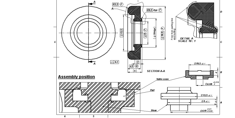
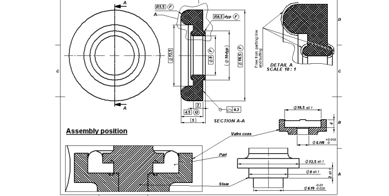
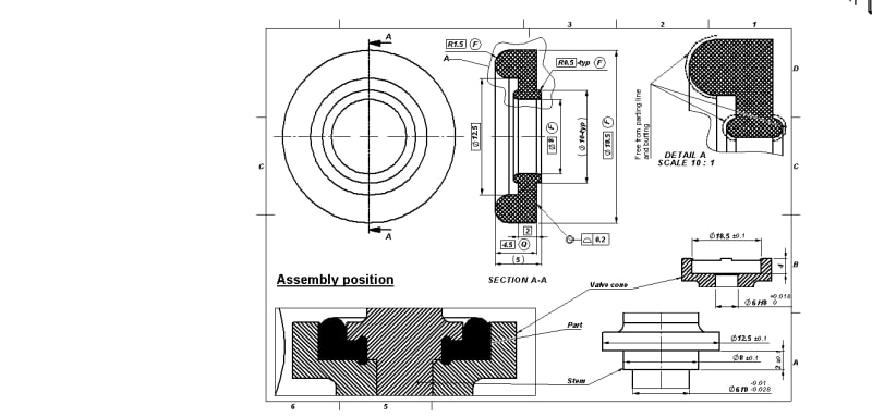
Flexible component with profile of surface
- Thread starter Sa-Ro
- Start date
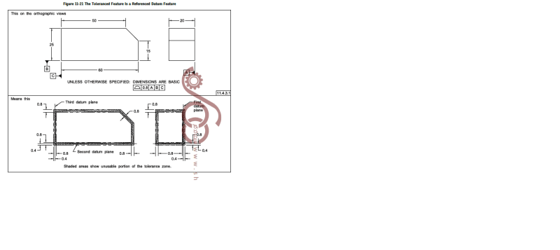
") and then paragraph 7.20 and its sub-paragraphs from the Y14.5-2018 standard.)
and then paragraph 7.20 and its sub-paragraphs from the Y14.5-2018 standard.)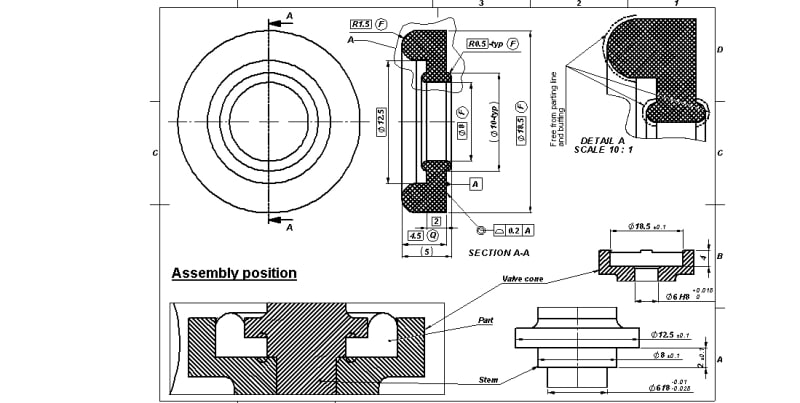
Similar threads
- Locked
- Question
- Question
- Locked
- Question