Tek-Tips is the largest IT community on the Internet today!

Members share and learn making Tek-Tips Forums the best source of peer-reviewed technical information on the Internet!

  • Congratulations MintJulep on being selected by the Eng-Tips community for having the most helpful posts in the forums last week. Way to Go!

Flange Buckling Restraint 1

Status
Not open for further replies.

KootK

Structural
Joined
Oct 16, 2001
Messages
18,690
Location
CA
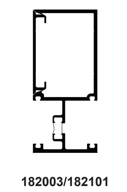
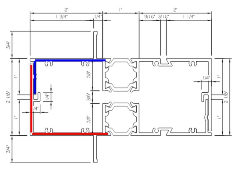
I'm evaluating the capacity of the split vertical mullion system shown below. For the evaluation of flange local buckling, I'm treating the blue and red flanges as though neither braces the other in any way. And that's resulting in very low capacities. Much lower, in fact, that the span charts of other manufacturers would indicate for similar products (Kawneer, Toro, etc).

So my question is this: could I rationally justify either the blue or red flange being braced against local compression buckling at their tips? Or could the red flange be considered to only cantilever from its "connection" to the blue flange? Treating the flanges this way, instead of as fully cantilevered from the side walls, makes a large difference with respect to capacity.

In the wild, I fully expect that this flange buckling would see some kind of restraint. Justifying that to be relied upon for a design assumption is another matter altogether however. There will eventually be some testing.

c01_dngpn7.jpg


I like to debate structural engineering theory -- a lot. If I challenge you on something, know that I'm doing so because I respect your opinion enough to either change it or adopt it.
 
I really don't know much about cold formed steel or alluminium strucutures but don't those small indentations on the walls, if continuous, provide additional lateral support to the walls? Maybe you could try to take them into account as a continuous lateral spring.

As far as how to analyse that, probably only with specialized software like CUFSM (Link) or CUTWP (Link).
 
A few questions/comments from a former curtain wall engineer -

Sounds like the issue may be case 3.4.11 from the ADM? If so, there are some common tricks to squeeze about more capacity.

a) typically the unbraced length will be taken between the horizontal members (assuming there are full depth)
b) often times we would consider using rye as defined in Section 4.9, as it often results in significantly higher results
c) sometimes if a negative corner zone wind pressure is controlling, looking at the moment capacity inward and outward can help

And if you are looking for a more technical, detailed approach on curtain wall lateral buckling, there is a article in the Journal of Structural Engineering (October 1989) by Clift and Austin that gets into great detail.

Hopefully there will be a performance mock-up, that will in the end justify your assumptions

Hope this helps

 
I was hoping that at CW or former CW guy would show up jjl317. Thank you every much for your help.
This is per Canadian code. That said, it's not Mars so whatever works in the ADM should work here. I'll scope out those provisions.

I believe that you're discussing lateral torsional buckling while, at present, I'm only looking at local buckling of the flanges. With that in mind, do you have any additional advice to offer? I'm trying figure out if I can use that snap together connection to any structural advantage. It obviously doesn't make the mullion a closed tube but, if it could at least brace the flange ends so that the flanges were "supported on two sides", that would make a huge difference. So far I'm not loving it. My suspicion is that manufactures are doing this though.

LTB is a whole other mess but, for now, I'm doing like the CW manufactures and pretending the glass can stabilize things with respect to LTB an weak axis buckling.


This article right? Link. If so, I was checking it out last night. If you say it's the way to go, I'll make the purchase.

What was holding me back from making the purchase was that I wondered if Clift's advice was still valid given 2010 ADM concerns regarding the use of glazing and gaskets as permanent structural bracing. See the blog post below from a notable CW engineer. I've been trying to determine if there's a similar provision in the Canadian codes. So far, I've not found anything. Our latest is only 2005 though.

@avscorrei: thank you for your contribution too. I agree but, if ends up requiring FEM, I'll be looking to bow out.

c01_lyhi2p.jpg


I like to debate structural engineering theory -- a lot. If I challenge you on something, know that I'm doing so because I respect your opinion enough to either change it or adopt it.
 
[blue](KootK)[/blue]

For the evaluation of flange local buckling, I'm treating the blue and red flanges as though neither braces the other in any way.

How are they connected (if at all)?

 
It's been awhile since I have been in the CW world, but I definitely agree with the post above about many of the commercial store front systems - buckling often neglected, and based purely on deflection.

On the local flange buckling, not sure how handled up north (and my apologies about the US assumption), but I don't remember considering any benefit of interlock for cases like this. Though I do remember many discussions about the benefits of the hook on the inside of the red flange.

In terms of Clift / ADM / ASCE and design "rules", unless something has changed, there were always holes in how to address custom interlocking extrusions.

And I attached a copy of the article (which I haven't really looked at in years - hope it's helpful)

Good luck

 
WArose said:
How are they connected (if at all)?

Only via mechanical interlock. Crazy, huh? It's actually the developers intent to have as much slop in it as possible to make it field tolerance friendly.

At first blush, I've been worried that there's little sense in bracing one flange that wants to buckle with another flange that wants to buckle. In reality, I could see it kind of working though. The two flanges would surely have different buckling wave lengths which would not coincide. Who wants to hang their hat on that though, of course.

I like to debate structural engineering theory -- a lot. If I challenge you on something, know that I'm doing so because I respect your opinion enough to either change it or adopt it.
 
jjl317 said:
And I attached a copy of the article (which I haven't really looked at in years - hope it's helpful)

It's very helpful, thanks so much.

jjl317 said:
and my apologies about the US assumption

No need, it's a perfectly reasonable assumption given demographics here.

jjl317 said:
Though I do remember many discussions about the benefits of the hook on the inside of the red flange.

Do you recall what those proposed benefits were? Structurally, I see the interlock issue that I've raised and, possibly, a stiffening effect as suggested by avscorreia. Some systems seem to have sealant in there which would surely improve matters. That, or I don't understand what I'm asking.

jjl317 said:
buckling often neglected, and based purely on deflection.

Do you think? I've been starting to suspect that the catalogs are based on deflection plus yield strength sans buckling. A lot of times they'll say something like "based on Fy = 15000 psi". With local/global buckling in the mix, it hardly seems that simple.

Have you any experience in estimating the shear modulus of the thermal break composites per AAMA TIR-A8-08? I'm struggling with the heat dependency of that stuff. I've been speaking with the manufacturer directly but I keep getting sales folks who don't really seam to understand what I'm asking. They give me 83 ksi whereas TIR seems to suggest a general range of 20-80ksi.


I like to debate structural engineering theory -- a lot. If I challenge you on something, know that I'm doing so because I respect your opinion enough to either change it or adopt it.
 
[blue](KootK)[/blue]

Only via mechanical interlock. Crazy, huh? It's actually the developers intent to have as much slop in it as possible to make it field tolerance friendly.

At first blush, I've been worried that there's little sense in bracing one flange that wants to buckle with another flange that wants to buckle. In reality, I could see it kind of working though. The two flanges would surely have different buckling wave lengths which would not coincide. Who wants to hang their hat on that though, of course.

If the "mechanical interlock" did not pinch the pieces together with a good amount of force (and it sounds like they don't).....I would consider them completely independent.
 
That's the direction I've taken so far. It's not making me popular though. A competitor has a similar product on the market that can span 10' supposedly at reasonable spacings. I'm getting more like 6' You can imagine how well that's been received. Hobbit specific marketing.

I've actually attempted to remove a curtain wall mullion beauty cap in the past with my bare, soft hands. It was surprisingly difficult.

The detail below is from Kawneer's catalog. I don't see how the top flange of that could possibly hold up unless it's assumed to be braced by its interlocking connection. I've tried like the devil to get in touch with their engineering department but they seem to keep those guys behind a pretty tight firewall. They always kick me back to a local sales guy.

c01_lvcy8r.jpg


I like to debate structural engineering theory -- a lot. If I challenge you on something, know that I'm doing so because I respect your opinion enough to either change it or adopt it.
 
[blue](KootK)[/blue]

That's the direction I've taken so far. It's not making me popular though.

It's good policy though. For flexural loads....it's just like any built up shape. (I.e. you need to nail it together. It can't be slipping.) For axial load, the pieces will try to separate as it approaches the buckling load.
 
KootK said:
So my question is this: could I rationally justify either the blue or red flange being braced against local compression buckling at their tips? Or could the red flange be considered to only cantilever from its "connection" to the blue flange? Treating the flanges this way, instead of as fully cantilevered from the side walls, makes a large difference with respect to capacity.
I would say the blue flange is unbraced. The red flange is braced at its midpoint by the blue flange to the extent that the blue flange is capable of bracing it.

BA
 
WARose said:
For flexural loads....it's just like any built up shape. (I.e. you need to nail it together. It can't be slipping.) For axial load, the pieces will try to separate as it approaches the buckling load.

Oh no, the two channels are most definitely not composite. The only use for the mechanical interlock would be local flange buckling prevention.

BA said:
The red flange is braced at its midpoint by the blue flange to the extent that the blue flange is capable of bracing it.BA

And that's the rub. How to assess the blue flange's ability to brace when it's prone to buckling itself?

I like to debate structural engineering theory -- a lot. If I challenge you on something, know that I'm doing so because I respect your opinion enough to either change it or adopt it.
 
[blue](KootK)[/blue]

Oh no, the two channels are most definitely not composite. The only use for the mechanical interlock would be local flange buckling prevention.

At that point I guess you'd be relying on the out-of-plane flexural strength/stiffness of the leg (of the blue & red pieces) to prevent buckling. Interesting problem.

One big issue would still be the lack of connection IMHO. If there really is that much "play" in this system (for ease of field fit)....wouldn't that mean whatever was having to be braced might have to buckle a bit before coming into contact with what is supposed to brace it? (I.e. due to any gap.) That's not going to be a good scenario.

 
WARose said:
wouldn't that mean whatever was having to be braced might have to buckle a bit before coming into contact with what is supposed to brace it? (I.e. due to any gap.) That's not going to be a good scenario.

Yeah, I've been wondering the same thing. Gaps are very small. 1/8" or less. I suppose it might be okay if things remained elastic and bounced back after buckling. I'd definitely be curious to know how the CW guys feel about this issue.

I like to debate structural engineering theory -- a lot. If I challenge you on something, know that I'm doing so because I respect your opinion enough to either change it or adopt it.
 
Only dabbled in aluminum, but being from Florida most of the mullions for glazing have been tested as assemblies, and we can get very high wind pressures. Perhaps you could take a look at the product approval website and check out what spans there are posted for different sections.

Link

There are alot of span tables and detail sheets at this website
 
KootK said:
And that's the rub. How to assess the blue flange's ability to brace when it's prone to buckling itself?

It would be very approximate. If we were dealing with steel shapes, we could consider the effective width of each flange. If that were greater than one inch (the length of blue flange), then the blue flange has some capacity to serve as a brace. Using the 2% rule, a permissible force per unit length applied at the end could be assigned to the blue flange based on its moment resistance. That could be used to increase the effective width of the red flange.

The critical buckling stress occurs in a different location than the maximum bending stress, so it seems reasonable to allow them to work together.

BA
 
In terms of the red flange, the 1/4" x 1/4" "hook" on the inside face could potentially be considered to reduce the b value in the b/t check (i.e. is b just the portion to the top - approx. 1" as opposed to full width - approx. 2")

Again, I have been away from it for a while, but from memory (and as shown in the Kawneer example), I always thought that the "snap" engagement of the interlocking pair worked against each other. In this case, it looks like the lower half (red) could just move to the left, without engaging the other half? Is this a new system, or an existing one?

And in terms of AAMA TIR-A8-08, we never used it, and instead used reduced properties for thermally broken systems, based on a 0.85 reduction factor for poured and debridged extrusions, and 0.9 for iso-strut. I can't say as I ever saw any documentation on how this was determined, but seemed to be somewhat of an industry standard.
 
jjl317 said:
Is this a new system, or an existing one?

It's a new product being developed.

jjl317 said:
I always thought that the "snap" engagement of the interlocking pair worked against each other. In this case, it looks like the lower half (red) could just move to the left, without engaging the other half?

That is correct. I've actually been struggling to get that very picture out of my head. That's what my imagine locks on to but, in truth, I don't think that's an actual picture of what local flange buckling is. LFB should be all outwards movement rather than side swing think. Still, were I to be brave enough to count on the hook in this way, I'd at least want to expand the overlap a bit.

jjl317 said:
based on a 0.85 reduction factor for poured and debridged extrusions, and 0.9 for iso-strut. I can't say as I ever saw any documentation on how this was determined, but seemed to be somewhat of an industry standard.

That's good to know and, based on my work so far, I'd say that's as accurate as anything else. I've done this the TIR way so far an boy is it hard. The capacity depends on the load which leaves me no way to generate capacity other than to resort to MathCAD's version of goal seek. I need to produce semi-continuous output for graph generation. Thankfully modern computers no longer seem to choke up on this kind of thing. I've actually got another thread going on that: Link. I struggle to wrap my head around why Sx is load dependent but Ix is not. I'm presently the first to admit that my understanding of sandwich thing mechanics is not as strong as I'd thought. It's also very hard to have faith the TIR method because it's so darn complex. In addition to the recursive business, it's all fifth order differential equations with terms that mean next to nothing to me. It took me a couple of days to get things ironed out at first just because TIR had some inconsistencies with their signage etc.

I like to debate structural engineering theory -- a lot. If I challenge you on something, know that I'm doing so because I respect your opinion enough to either change it or adopt it.
 
Status
Not open for further replies.

Part and Inventory Search

Sponsor

Back
Top