Navigation
Install the app
How to install the app on iOS
Follow along with the video below to see how to install our site as a web app on your home screen.
Note: This feature may not be available in some browsers.
More options
Style variation
-
Congratulations MintJulep on being selected by the Eng-Tips community for having the most helpful posts in the forums last week. Way to Go!
You are using an out of date browser. It may not display this or other websites correctly.
You should upgrade or use an alternative browser.
You should upgrade or use an alternative browser.
Fig 6-19 - ASME 1994 and orientation (profile versus position) 2
- Thread starter aniiben
- Start date
- Status
- Not open for further replies.
powerhound
Mechanical
Profile tolerance controls the perpendicularity of the walls to A. I might agree with drawoh that the boundary created by the position tolerance will probably restrict the orientation to B and C before the profile tolerance IF the feature is at it's MMC size; however, at LMC it will be a close call to figure out which boundary restricts orientation to B and C first (inner or outer.
John Acosta, GDTP Senior Level
Manufacturing Engineering Tech
John Acosta, GDTP Senior Level
Manufacturing Engineering Tech
powerhound
Mechanical
Probably because the inner boundary is already oriented to A via the position callout. The walls can be in any location and orientation within the profile tolerance zone and the inner boundary cannot be violated. I don't think this is an incorrect callout. It's definitely different from the 1994 figure though.
John Acosta, GDTP Senior Level
Manufacturing Engineering Tech
John Acosta, GDTP Senior Level
Manufacturing Engineering Tech
-
2
- #7
pmarc
Mechanical
- Sep 2, 2008
- 3,248
pylfrm said:I am curious. What lead you to ask this question?
Maybe it is the wording of associated paragraph in the standard (6.5.5.1):
"In this example [fig. 6-19], the basic dimensions and the profile tolerance establish a tolerance zone to control the shape and size of the feature."
Because of presence of A in the profile callout, that statement seems incomplete at best.
By removing A from the profile callout in the 2009 standard, this problem was solved.
However, pmarc, having datum A in the profile tolerance at least allowed the two geometric tolerances to be measured on the same primary plane. Perhaps that made it easer for gaging; just drop the part onto a table, and it would be a simple matter to engage B and C when needed for the position measurement.
But I agree that the actual relationship to datum A is controlled by position, and you make a good point about the picture now matching the text description.
John-Paul Belanger
Certified Sr. GD&T Professional
Geometric Learning Systems
But I agree that the actual relationship to datum A is controlled by position, and you make a good point about the picture now matching the text description.
John-Paul Belanger
Certified Sr. GD&T Professional
Geometric Learning Systems
greenimi
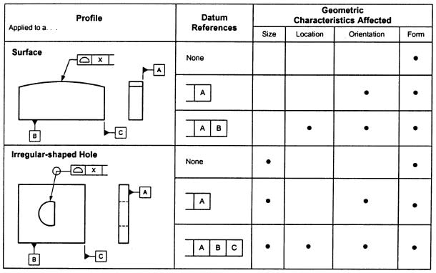
With the presence of A in the profile callout, it will not only control the shape and size geometric characteristics but also the orientation, the table below is a good reference. (quote from Alex's Advanced Concepts of GD&T page 22-9)
Thanks pmarc lead me to look at this table, you catched the point shape and size.

Since some answers were addressed directly to me (even I am not the one who asked the original question) I would say that having datum feature A in the profile is a mistake in the standard (rectified by the 2009 revision). In the court of law only the text (and yes, not the pictures) counts and considered in a legal argument. Pictures only help visualize the concept.
That is my opinion based on pmarc's referenced paragraph from 1994.
That is my opinion based on pmarc's referenced paragraph from 1994.
- Status
- Not open for further replies.
Similar threads
- Question
- Replies
- 8
- Views
- 13K
- Replies
- 25
- Views
- 2K
- Locked
- Question
- Replies
- 6
- Views
- 894
- Replies
- 12
- Views
- 11K
- Question
- Replies
- 2
- Views
- 612
