According the calculation of actual_value = size_MMC - size_RAME we get: actual_value = 9.8 - 9.71 = 0.09, pretty close to t0 of 0.1 and pretty close to be rejected, because of the effect of its size during the evaluation of position conformance (position with any kind of modifier in the feature control frame is still a control position: I.e. location and orientation)
The value of 0.09 just says that some portion of the feature is 0.1-0.09=0.01 away from violating virtual condition. It does not matter if that means all points on the feature are this far away from the virtual condition as in your example or if only a small portion is this far away (a larger hole, offset slightly resulting in the same RAME) - the result will be the same. Your suggestion would produce different actual values in both these cases even though neither would be any closer/further from violating virtual condition.
I do realize that the main goal of MMC tolerances is to make sure a fixed boundary is not being violated by the feature.
Its not just the main goal, its the very definition. From Y14.5-2018 "5.9.4.1 Explanation of the Surface Method. When a geometric tolerance is applied on an MMC basis, the feature’s surface shall not violate the VC boundary."
But if we have two different interpretations to the same geometrical tolerance and one is an approximation of the other as you say, wouldn't it make sense for the actual value calculations for both interpretations to produce results that are similar or close enough to each other?
Yes it would make sense. This is why if I've said several times that in my mind the minimum t
0 should be the actual value for both interpretations as it would accomplish what you say, however I have to work with what the wording of the standard says. While I don't know why they changed the definition of actual value for the axis interpretation, its not terribly critical as we know that it is but an approximation of conformance as the surface interpretation takes precedence.
What doesn't make sense to me is trying to get the surface interpretation to replicate the current definition of actual value for the axis interpretation (minimum value of b = D) by involving the UAME size. While inherently not making sense to me (trying to get the surface interpretation to match the axis interpretation results) it falls apart when increasing form error is introduced.
If we take a look at the cases below, when form error is introduced comparison of the UAME and RAME provides no relevant information as well as doesn't match the axis interpretation actual value (as we know). In reality this definition of actual value (size_UAME - size_RAME) has little use when considered by itself, and is only really useful in comparison with your "total allowed tolerance" (t
0 + size_UAME - size_MMC). I already showed that when compared, the size_UAME term cancels out and is not necessary.
In both the below, lets take the theoretical specification of:
dia. 10 +0.8/-0.2
|POS|dia. 0(M)|A|B|C|
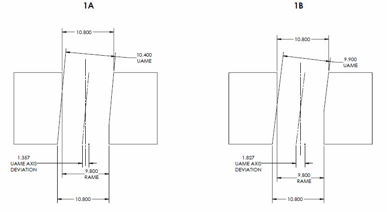
1)
Y14.5.1 surface interpretation (both) actual_value = size_MMC - size_RAME = 9.8 - 9.8 = 0
Your surface interpretation proposal (1A) actual_value = size_UAME - size_RAME = 10.4 - 9.8 = 0.6
Your surface interpretation proposal (1A) total_allowed_tolerance = t
0 + (size_UAME - size_MMC) = 0 + 10.4 - 9.8 = 0.6
Your surface interpretation proposal (1B) actual_value = size_UAME - size_RAME = 9.9 - 9.8 = 0.1
Your surface interpretation proposal (1B) total_allowed_tolerance = t
0 + (size_UAME - size_MMC) = 0 + 9.9 - 9.8 = 0.1
Y14.5.1 axis interpretation (1A) actual_value = D/2 = 1.357/2 = 0.6785
Y14.5.1 axis interpretation (1A) tolerance_zone = 0.6*
Y14.5.1 axis interpretation (1B) actual_value = D/2 = 1.827/2 = 0.9135
Y14.5.1 axis interpretation (1B) tolerance_zone = 0.1*
As you can see from the features shown by 1A and 1B, neither is any closer/further from violating virtual condition however both your proposal and the axis interpretation produce wildly different results. This is why the comparison of the UAME and RAME is only useful in cases of perfect form. What do the values of 0.6 and 0.1 tell us? It does not agree with the axis interpretation due to the form error. In fact, the latter which should be "more perfect" in your definition (size_UAME nearing size_RAME) actually results in a UAME which is even further from being coincident to the RAME (shown by the axis interpretation actual_values of 0.6785 and 0.9135).
Your proposal for actual value is only useful when compared to the "total allowed tolerance" (0.6-0.6=0 or 0.1-0.1=0) because, as I showed earlier, the size_UAME term cancels out and you are left with the current definition of MMC surface interpretation.
*same as your "total_allowed_tolerance"
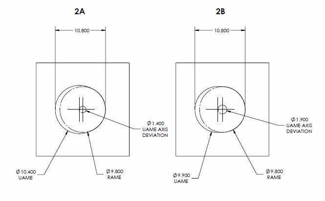
2) Same calculations as case (1) except for the below
Y14.5.1 axis interpretation (2A) actual_value = D/2 = 1.4/2 = 0.7
Y14.5.1 axis interpretation (2B) actual_value = D/2 = 1.9/2 = 0.95
A similar case as (1) however with a UAME axis parallel to the RAME. As you can see, the UAME can be located as far from the RAME as the limits of size will allow and the relative size of the UAME and RAME tells us just as little as it does in case (1).
If the produced feature fulfills the condition that the envelope of RAME is coincident with the envelope of UAME, this is a feature that I consider to be produced "perfectly" in terms of the surface interpretation MMC position (and note that I didn't mention the feature axis)
As I've shown above, comparison of the size of the UAME and RAME does not guarantee that they are coincident. I left the UAME in my examples slightly larger than the RAME (9.9 in both cases) however if you change it to either the same as the RAME (which would produce two solutions for the UAME - which is theoretically possible but realistically unlikely) or infinitesimally larger (9.8000001) the result is the same.