Continue to Site

Eng-Tips is the largest engineering community on the Internet

Intelligent Work Forums for Engineering Professionals

  • Congratulations KootK on being selected by the Eng-Tips community for having the most helpful posts in the forums last week. Way to Go!

Fig 5-5 straightness per unit length 2

Status
Not open for further replies.

aniiben

Mechanical
May 9, 2017
165
Y14.5-2009 page 94

Does anyone have an insight on how 0.1, 0.4, 0.9 and 1.6 values in fig 5-5 are driven from fig 5-4 straightness geometrical control?
Not very sure I understand the idea of the "per unit basis".

 
Replies continue below

Recommended for you

aniiben,

If I'm reading that figure and the accompanying paragraph correctly (end of 5.4.1.3), figure 5-5 shows a possible outcome if the straightness tolerance in figure 5-4 was only specified 0.1/25 (ie: per unit length basis only) and the total straightness tolerance of 0.4 was omitted.

The way the figure on 5-5 is drawn, without accompanying explanation, is a little confusing but this is how I interpret it. The straightness when measured over each 25mm section will be 0.1* (0 to 25 section, 25 to 50 section, etc..), but when measured over the entire length can be as much as 1.6 (0 to 100). The maximum straightness deviation of the shape shown occurs in the middle of each section. That is 0.1 deviation occurs at 12.5 (halfway between 0 and 25 section), 0.4 deviation occurs at 25 (halfway between 0 and 50 section), 0.9 deviation occurs at 37.5 (halfway between 0 and 75 section), and finally 1.4 deviation occurs at 50 (halfway between 0 and 100).

*Edit: I should clarify that this straightness per unit length (0.1/25) obviously applies to any 25mm section taken along the feature's length, not just the ones I noted.
 
It's a place holder for curvature control, mostly because it's assuming that the main use is something that is not constant curvature so all you need to get a quick rough check is a flat surface of limited length and a feeler gauge.

The numbers are just the distance from the chord line to the arc at various locations.

I did a GeoGebra diagram. It works out to a radius of 781 mm/ curvature of 0.00128/mm


The diagram is not completely parametric; the chord needs to be adjusted as I don't know of a chord function. If the chord length changes or the straightness changes the user will have to manually move Point D.
 
3DDave you inspired me to determine the solution analytically. I was going to do that initially but figured my simple explanation might suffice, however I realize now it doesn't do a great job of explaining the geometry involved.

Where:
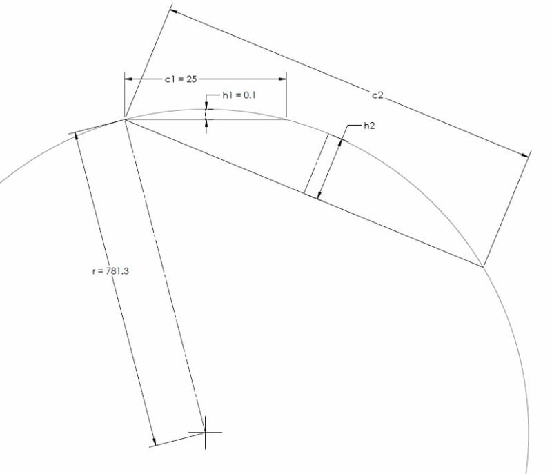
r is the radius of curvature
h1 is the straightness tolerance applied
c1 is the per unit length over which straightness tolerance is applied
c2 is the the length of the segment desired to be analyzed (in the figure 5-5 this is shown as 50/75/100)
h2 is the straightness deviation allowed over length c2 due to straightness tolerance h1/c1

h1 = 0.1
c1 = 25

to find the radius of curvature

r = (c1^2)/(8*h1) + h1/2 = 781.30

then

h2 = r - r*cos((2*asin(c2/(2*r)))/2)

For the values shown in the figure c2 = 50 / 75 / 100, h2 = 0.40008 / 0.90046 / 1.6015 respectively.

Its interesting to note that the resulting deviation over the entire length of the feature is more sensitive to the length over which the initial tolerance zone is specified than the diameter/width of the tolerance zone itself. This is because in the equation for the radius of curvature the per unit length c1 (actually the chordal length) is to the power of 2 whereas the size of the tolerance zone h1 (actually the distance from the chord to the arc) is to the power of 1. For example if the size tolerance was twice as loose (0.2mm per 25mm) the resulting deviation over 100mm would be 3.2124 (radius of curvature is now 390.73mm) whereas if the per unit length was twice as loose (0.1mm per 12.5mm) the resulting deviation over 100mm would now be 6.5067 (radius of curvature is now 195.36mm).

Perhaps the below figure can connect the figure provided in the standard (5-5) with my equation/explanation for OP. Obviously the dimensions are not to scale - I had to fudge the scaling so that you could visualize the distance from the chord to the arc, otherwise it was very difficult to see.

Edit: Just a few formatting changes for the subscripts (and one mistaken reference where I put c1=50/75/100 where it should have been c2=50/75/100), I realized h1 instead of h1 is easier to read in a formula. Note to self - maybe avoid subscripts in the future and instead use unique variables..

straightness_per_unit_length_gxzqst.jpg
 
aniiben,

I am interested to know whether the explanation/figure helped in understanding the topic? Hopefully it didn't create more confusion than it was meant to solve..
 
Important to give credit when credit is due. Thank you chez311.

Just a quick question:

Why there some extra "two's" in your formula?

h2 = r - r*cos((2*asin(c2/(2*r)))/2)

h2 = r - r*cos(([highlight #F57900]2*[/highlight]asin(c2/(2*r)))[highlight #F57900]/2[/highlight])


Extra 2's highlighted. Or they're not extra? Trying to get the correct numbers.
 
aniiben,

Glad it could help and glad you asked the question! I just wasn't sure if it had helped make it clearer or muddied the waters.

In regards to the equation you are absolutely correct - thats a miss on my part. It can be restated as follows with the same result:

h2 = r - r*cos(asin(c2/(2*r)))
 
Status
Not open for further replies.

Part and Inventory Search

Sponsor