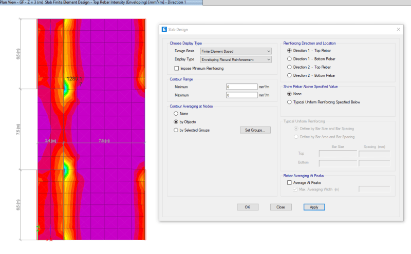
To me, the issue is that the FEM analysis shows you what the moment is at an infinitesimally small width al the wall locations. There are a number of ways I have dealt with this in the past. I kind of invented my own terminology when I was writing this up (back when I was working on the development and documentation for RISAFoundation). The methods I came up with were the following:
ACI Definition of Strips (ACI 318-14 Section 8.4.1/ACI 318-11 Section 13.2)
This section of the ACI code is really intended for elevated slabs. The requirement for "column strips" is that the width on each side should be set to 25% of the span length or width whichever is smaller. Then the "middle strip" is defined to span between the edges of the column strips.
This method requires engineering judgment for column grids that are not perfectly aligned and rectangular. In addition, when the column strip becomes very small then the middle strip may become very wide so that the entire slab is included in either a column strip or a middle strip.
The ACI strip method listed above is based on essentially 1/2 of the mid-span tributary lines. The hand calculation methods would have you design for the full tributary moments over this smaller width which should be conservative. Computer methods will design for the average moment over the assumed design width which should result in a more efficient design.
Zero Shear Transfer Method
The Zero Shear Transfer method used the shear force contours perpendicular to the span of the slab to set the design width. This should provide a result very similar to using the mid-span tributary lines, but is a bit more theoretically derived for non-rectangular column layouts. This method is described in greater detail in the PTI publication Design Fundamentals of Post-Tensioned Concrete Floors. Ideally, this method should give design strips of similar width to the ACI strip method. However, it is more rationally derived and should work better for cases where uneven column spacing makes the strip method difficult to apply.
Zero Moment Method
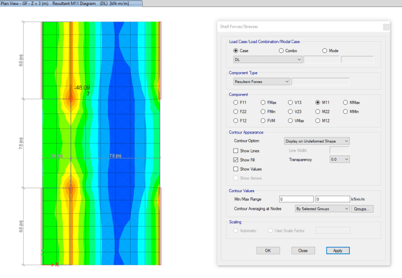
In a similar fashion to the zero shear transfer method, the Zero Moment method uses the moment contours to identify where the moment changes sign. This can be used to set the design strip width approximately equal to the distance between zero moments.
Shear Perimeter Method
Another basis would be to set the design width equal to the pedestal width plus a distance 'd' or 'd/2' on each side (in your case wall width + d or d/2). This will end up being a more conservative assumption for flexure than the other methods listed. As such, it would be more appropriate for situations where shear or punching shear failures are a primary concern. Examples would also include cases where the pedestal is very large such as for a vertical vessel or grain silo.
Hybrid Method / Engineering Judgment
A variation on these methods would be to start off setting the column strip using the ACI strip method. Then, if necessary, the width could be modified based on considering the other methods. This is especially true for situations where the column grid is not aligned or rectangular.
In addition, when the middle strip widths get too large, they could be set to values closer to the column strip width. The middle strip would normally be centered on the area with the highest mid-span moments. This would neglect lower moment regions between the column and middle strips. Hence the strips would designed for a higher moment per unit width. This reinforcement could then be extended into the lower moment regions between strips.