Tek-Tips is the largest IT community on the Internet today!

Members share and learn making Tek-Tips Forums the best source of peer-reviewed technical information on the Internet!

  • Congratulations JAE on being selected by the Eng-Tips community for having the most helpful posts in the forums last week. Way to Go!

FEA modelling of beam vs slab (in SAFE for example) 1

Status
Not open for further replies.

canadiancastor

Structural
Joined
Apr 13, 2014
Messages
39
Location
CA
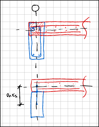
Trying to explain this to someone else, I found out there is a gap in my knowledge. I can't find any information about it in SAFE documentation, but it's really a quite simple question. When beams are modelled in SAFE, there must be an area where the beam and the slab are overlapping? How does SAFE deal with the area that is duplicated (see red hatched area below)? The only thing I could think of would be to have a smaller beam modelled "beneath" the slab with rigid links into the slab, but I don't think this is what they are doing (bottom sketch).


PP_2024-03-14_08-52-02_vxgev9.png
 
I don't know the answer, but I'd recommend building a small and very simple model and comparing the SAFE results to manual calculations.

Another question is what does it do with the stiffness. The MOI of the edge beam is a lot different if the beam centroid is at the slab centroid versus pushed down to its actual location. I'd test that out with the simple case also.
 
I've looked into this for SAFE. That area is double counted (this comes from csi tech support). In SAFE there is an option to convert frame elements to slab elements, it will create a slab "drop" property of the corresponding thickness and replace the frame element. In that case it would not be double counted. Also check out the option in safe to ignore or not ignore the "offset", that has a big difference on behavior.
 
Status
Not open for further replies.

Part and Inventory Search

Sponsor

Back
Top